Stem Seal Replacement Bulletin
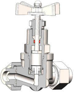
Every new CPV O-SEAL® valve provides leak-proof assurance to up 6000 PSI (413 bar). Properly maintained they should provide long, reliable service. The stem seals are made of Viton®, Polyurethane, Ethylene Propylene, etc. and should be inspected at appropriate intervals depending on system conditions and frequency of use. To maintain CPV’s leak-proof standard after stem seal replacement, the “U” cup installation tool developed by CPV should be used. This tool is easy to use and enables users to replace a stem seal in less than a minute. By compressing the outer sealing lip and expanding the inner lip, the kit makes it easy to slip the “U” cup stem seal over the valve stem. Once the stem seal is properly installed on the valve stem, it can be easily inserted into the bonnet gland and secured without damaging the critical edges of the seal. A CPV Replacement Soft Goods Kit can also be ordered in the pipe size and soft goods material specified for the user’s application. This kit contains one of each: stem seal, body O-Ring, back-up ring, and seat O-Ring.
| Dash Number | Pipe Size | Tube Size | Tool Part No. | Stem Seal Part No.* |
|---|---|---|---|---|
| -0 -1 |
1/8 1/4 |
1/4 3/8 |
056930 | 001905-* |
| -2 | 3/8 | 1/2 | 056932 | 001909-* |
| -3 -4 |
1/2 3/4 |
3/4 1 |
056933 | 001919-* |
| -5 | 1 | 1 1/4 | 056935 | 001927-* |
| -6 | 1 1/4 | 1 1/2 | 056936 | 001935-* |
| -7 -8 |
1 1/2 2 |
2 2 1/2 |
056937 | 001953-* |
*Be sure to specify the stem seal material desired by adding the appropriate suffix (dash number):
|
||||
The CPV “U” Cup Installation Tool can be used on O-SEAL® Shutoff, Needle, or Stop-Check valve cartridges.
The relevant part numbers are as follows:
- Shutoff: 365, 370, 371, 380, 381, and 382
- Needle: 465, 470, 471, 480, 481, and 482
- Stop-Check: 565, 570, 571, 580, 581, and 582
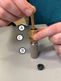
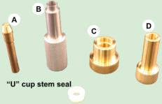
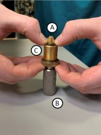
1. Insert items A and C onto item B.
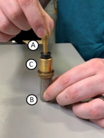
2. With the sealing lips facing away from the tool, slide the “U” cup over the taper on item A.
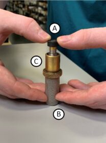
3. Continue to press the “U” cup over the item A until the cup is stopped by the shoulder of item B. At the same time, pull up on item C until it covers the “U” cup.
4. Remove item A.
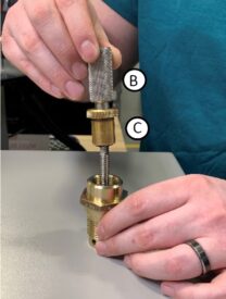
5. Invert items B and C with the “U” cup. Slip the tool assembly over the valve stem and into the bonnet gland.
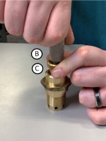
6. Hold down item C while removing item B.
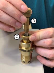
7. Insert item D.
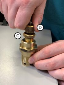
8. Press down on item D to seat the “U” cup in the gland. Remove the tool assembly