Selecting the Right Flow Control Valve: A Guide for Operators

Water flows, winds flow, and manufacturers prefer flow production, a term to describe the smooth and orderly movement of materials and components through the facility. The flow production method promotes efficient, streamlined output, and that means all components and systems must work in concert to achieve these efficiencies.

Flow control valves, although small components, are mighty in terms of keeping production flowing smoothly in chemical processing and other industry segments, as they regulate and direct the flow of liquids, gases, or slurries through piping systems, preventing disruptions and maintaining optimal process conditions.

Some of the most common industries that regulate gas flow for example, in addition to chemical processing, includes the food and beverage sector, pharmaceutical and biotechnology applications, water/wastewater management, oil and gas, industrial gas, and the energy and power industry.

At the heart of any well-designed system is a minor yet critical component—the flow control valve. Flow control valves not only control the flow, as the name implies, but also the volume, direction, rate, and pressure of fluids and gases. As such, the flow control valve impacts the plant’s safety and efficiency, its production and profitability.

However, selecting the appropriate flow control valve can pose a complex and challenging task due to the need to balance multiple, often competing system requirements and operating conditions. This selection of a seemingly simple component is complex due to:

  • The multiple factors requiring consideration, such as flow rate, pressure, fluid properties, control characteristics.
  • System-specific needs that might require a tailored valve solution.
  • Potential for unintended and undesirable consequences from an improper selection.
  • Technical expertise required to properly evaluate and size the valve.
  • Evolving system conditions over time.

The flow control valve needs to be carefully matched to the unique and sometimes changing demands of the fluid system. All the relevant specifications and known or anticipated operating conditions must be considered and balanced to select a valve for the most reliable, efficient and safe operation.
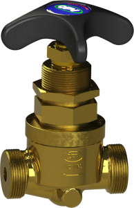
CPV Flow Control Valve

Properly sizing and matching the valve

As an operator, the biggest hurdle when choosing a flow control valve is selecting the proper size and matching it to specific system requirements. The wrong selection could generate many issues – from insufficient flow capacity to excessive pressure drops, control instability to premature wear and reliability problems. Carefully evaluate the key factors to select the proper flow control valve for optimal performance and long, trouble-free service life, for a true “set it and forget it” component.

  • Determine your flow requirements

    The first and most fundamental step is to accurately define your flow requirements. This means knowing the minimum, maximum and ideal flow rates you need the valve to handle. Consider not just your current needs, but any potential future changes or expansions to your system. Underestimating your flow requirements can lead to an undersized valve unable to meet your process demands. Conversely, overestimating can result in an oversized valve that creates excessive pressure drops and control challenges.

  • Evaluate fluid properties

    The physical properties of the fluid flowing through the valve can impact valve selection and performance. Factors like fluid viscosity, density, temperature and phase (liquid, gas, or two-phase) must be considered.

    More viscous or dense fluids will require larger valve sizes to maintain the same flow rates as less viscous fluids. The potential for issues like cavitation and flashing must also be carefully evaluated based on the fluid’s vapor pressure characteristics.

  • Assess pressure requirements

    Closely related to a system’s flow requirements are the pressure conditions. Operators should know the upstream and downstream pressures and the maximum allowable pressure drop across the valve. These pressure parameters will help dictate the valve size, trim and actuator needed to provide the required flow control while maintaining suitable pressure conditions. Ignoring pressure requirements can lead to control instability, component damage and safety hazards.

  • Factor in valve sizing and materials

    With the flow, pressure and control parameters defined, you can begin sizing the valve. This requires careful hydraulic or pneumatic calculations, computerized flow modeling, and close collaboration with the valve manufacturer like CPV Manufacturing.

    The right valve size is critical – too small and you will restrict flow, too large and you will battle instability and cavitation. The valve materials of construction must also be compatible with your process fluids to ensure long-term reliability and avoid corrosion or erosion issues.

  • Do not forget installation and maintenance

    Even the most carefully selected valve can underperform if the installation and maintenance practices are suboptimal. Factors like upstream and downstream pipe configurations, valve orientation, and accessibility for servicing must all be considered during the installation phase. Ongoing monitoring, adjustment and preventative maintenance are also essential to keep your flow control valve operating at peak efficiency throughout its service life.

The consequences of getting it wrong

Selecting the wrong flow control valve for your application can have serious consequences. An undersized valve will be unable to meet your flow demands, potentially starving critical equipment and disrupting your entire process. An oversized valve, on the other hand, can create excessive pressure drops, control instability, and cavitation-induced damage. Both scenarios can lead to reduced efficiency, higher energy consumption and compromised system reliability.

Partnering for success

Given the complexity involved, operators are well-advised to work closely with experienced valve manufacturers and distributors when selecting flow control valves. Their technical expertise, application knowledge and sizing tools can be invaluable in ensuring you choose the right valve for your specific needs. Do not be afraid to lean on their guidance – it could mean the difference between a smoothly running, reliable fluid system and one plagued by persistent control and performance issues.

CPV Manufacturing focuses its efforts on fabricating and supplying high-quality valves, fittings and supplemental equipment for demanding applications like the naval and aeronautics industries. CPV can offer tailored solutions crafted with care, or more standard valves in a wide range of sizes.

By partnering with our experienced team of engineers, we can collaborate with your team to select and meet your unique requirements for reliable, precise flow control of industrial gases or liquids. Learn more about our extensive product line of valves and fittings. Or speak to a member of our staff to discuss the specifications for your next project.

Be thorough in your analysis and do not hesitate to seek expert support. Get the valve selection right, and you will enjoy trouble-free operation and optimal performance from your fluid system for years to come.

Preventing Check Valve Failure – Best Practices

Check valves play the role of unsung hero, silently managing the unidirectional movement of substances and thwarting the menace of backflow. Check valves are found within the intricate web of industrial processes, where fluid and gas flow dictate the rhythm of operations. Yet despite its straightforward function, a check valve failure can unleash a cascade of consequences, from compromising system integrity to costly equipment damage.

Recognizing the pivotal role of check valves to maintain operational efficiency, process engineers can follow best industry practices to avoid check valve failure. This blog discusses how to recognize the purpose of check valves, identify symptoms of malfunction and explore underlying causes of failure.

What is the function of a check valve?

A check valve employs a straightforward yet effective mechanism to restrict flow within piping and equipment to a single direction. Typically, a check valve consists of a hinged or spring-loaded disc in the body. When gas or fluid flows in the desired direction, the pressure of the incoming flow pushes against the disc, causing it to open or move away from its seat, allowing the fluid to pass through the valve. This forward movement must be of a sufficient pressure to overcome the resistance of the spring and the weight of the disc.

However, in the event of reverse flow, the pressure differential causes the disc to close against the seat, preventing backflow. Stainless steel, brass, or bronze often serve as preferred materials for check valve fabrication. An O-ring helps seal the seat, and springs are used to aid with secure closure. This design serves to enhance the valve’s functionality and reliability for establishing one-directional flow and preventing backflow.

Many industries and processes rely on check valves including:

  • Chemical processing
  • Oil and Gas / Refining
  • Industrial Gas
  • Waste and wastewater treatment facilities
  • Power generation
  • Marine and shipbuilding
  • Food and beverage
  • Commercial HVAC and plumbing

What are the symptoms of a bad check valve?

  1. Leakage: One of the most common symptoms of a bad check valve is leakage, which can manifest as loss of pressure within the system or external leakage around the valve itself. This leakage may lead to inefficiencies in system operation and even potential safety hazards.
  2. Pressure Fluctuations: A malfunctioning check valve can result in deviations from normal operating pressure within the system. These fluctuations may indicate improper sealing or flow reversal, compromising system performance and stability.
  3. Visual Indicators: Corrosion, rust or debris accumulation on the exterior of the check valve can serve as visual indicators of potential internal issues. These signs suggest deterioration or damage to the valve components, affecting its functionality and reliability.
  4. Condensation or Wetness: Presence of condensation or wetness around the check valve may indicate leakage or improper sealing, leading to fluid bypass and potential system inefficiencies.
  5. Inconsistent Operation: Changes in the way the check valve operates, such as failure to open or close properly, can be indicative of internal damage or wear. These inconsistencies may disrupt fluid flow and compromise system integrity.

By recognizing these symptoms, operators can identify potential issues with check valves and take appropriate measures such as inspection, maintenance or replacement to ensure optimal system performance and reliability.

What are the primary causes of check valve failure?

Check valve failure can stem from either external factors or internal mechanisms. External factors such as extreme operating conditions, including high temperatures, pressure fluctuations or exposure to corrosive substances can accelerate material degradation and compromise the structural integrity of the valve components.

Initial material selection for a check valve should consider the environment and known or anticipated operating conditions, to avoid these issues and achieve a longer lifespan and reliable service. Select a high-quality material to prevent issues such as corrosion or metal fatigue.

Additionally, inadequate installation practices or improper system design may lead to misalignment, excessive stress or fluid turbulence, exacerbating wear and tear on the valve and contributing to premature failure.

Internally, mechanisms such as spring fatigue from excessive cycling or disc deformation over time can diminish the valve’s ability to maintain proper sealing and prevent backflow effectively. Moreover, the accumulation of debris, scale, or sediment within the valve can obstruct flow passages, impede valve movement, and ultimately lead to malfunction.

How can I reduce the risk of check valve failure?

A properly specified and installed check valve should last for several years. A check valve is one of the rare “set-it-and-forget-it” components that help ease maintenance responsibilities that also keeps capital equipment humming. Despite the general lack of maintenance these valves require, here is a short list of tips to help reduce the risk of failure.

  • Proper Specification: This has been discussed, but since prevention is worth an ounce of cure, it’s worth mentioning again. Specify the proper materials for both the check valve and O-ring to avoid future problems, considering factors such as system temperature, pressure and gas composition.
  • Maintenance: visually inspect the check valve and conduct pressure and temperature checks. Watch for signs (listed above) that might indicate an issue with the check valve, such as pressure loss.
  • Component Replacement: Certain soft goods such as O-rings can wear out. Proactively replace these at any sign of wear, in adherence to manufacturer specifications to maintain optimal performance.
  • Quality Assurance: Source check valves exclusively from reliable manufacturers with a reputation for quality, service and experience.

Check valves help maintain the integrity and efficiency of fluid systems across various industries to direct the flow in one direction and prevent backflow. Companies rely on CPV Manufacturing for valves due to its sole focus on the design, fabrication and modification of valves of various types that serve diverse industrial purposes.

Our soft-seated, bubble-tight shut-off meets or exceeds the most stringent industry standards, including the established ASME Boiler and Pressure Code. CPV’s spring-actuated check valve design responds swiftly and precisely to pressure changes, to prevent reverse flow and guard against pressure surges, to safeguard equipment and system lifespan. Enjoy leak-proof performance and protect your system from contamination with a check valve from CPV.

CPV’s New CFC-50 Cryogenic Check Valve Is Ideal for Cold Flow Industrial Gas Applications – And Is In Stock!

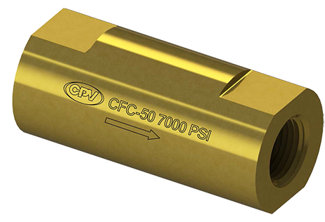
CPV Manufacturing introduces its newest line addition, the CFC-50 cryogenic check valve, optimized for numerous cryogenic and non-cryogenic industrial gas applications. It features a compact, inline design for strength and durability and offers excellent resistance to cold flow. The standard, off-the-shelf model CFC-50 is rated for 7000 PSIG (483 BAR) and a temperature range of -400° F to 380° F (-240° to 194°C).

CPV prioritizes parts availability to keep customers in supply when every day of downtime can have critical consequences for business operations and profitability. This new valve fulfills a need expressed by customers for an available, reliable inline valve that meets specifications for gas filling operations that handle cryogen and hydrogen, among other types of gases.

Chemical compatibility a key consideration

The new CFC-50 valve features a body and retainer fabricated with naval brass, for a long service life. The guide portion of the valve utilizes Kel-F® (PolyChloroTriFluoroEthylene), a unique fluoropolymer that offers excellent mechanical and physical properties and a high degree of chemical resistance.

PCTFE is also known for its low thermal expansion coefficient, making it an ideal polymer for use in lower temperatures. Its broad range of chemical compatibility compared to other fluoropolymers make it an ideal choice for gas filling and handling operations subject to temperature extremes.

Excellent flow rate without backflow concerns

The valve’s flow coefficient of 3.53 Cv translates into better control of the flow rate, or greater flow with less pressure drop across the valve. This can improve system performance and reduce energy consumption. The high Cv value also helps reduce wear and tear on other system components, such as pumps, by reducing the need for higher pressure differentials to achieve the desired flow rate.

Similar to other check valves manufactured by CPV, this new valve helps prevent water hammering or backflow, superior to other valves in the market due to the lack of rattling or vibration. This valve is designed for cryogenic and non-cryogenic industrial gas services, including the critical requirement of bulk tanks and gas filling applications, liquid natural gas (LNG) or the petrochemical industry.

In a cryogenic gas filling operation, for example, an inline check valve prevents the gas from flowing back into the storage tank or supply line when the filling process is completed. At its core, the valve features a spring assisted disc that shut off the valve when forward flow stops.

The valves are designed for smaller sized pipelines of up to two inches. Types of gases handled at industrial gas filling operations could include hydrogen, oxygen, nitrogen (the gas commonly used in cryogenic applications), argon or even methane, which can be stored in cryogenic liquid form.

Higher pressure ratings expand service application potential

In terms of pressure, some customers, especially in the hydrogen service area, are looking for valves that can handle higher ratings of 10,000 or even 15,000 psi. The alternative fuels market is pushing increased hydrogen demand, as it replaces fossil fuels for vehicles and transportation purposes.

Technologies associated with these hydrogen applications require high pressure ratings compared to other types of services. While the new CFC-50 cryogenic check valve is currently rated up to 7,000 psi, but for custom orders, CPV can modify the material to enable pressure ratings of 10,000 psi.

Cryogenic technology and equipment demands

Globally, the cryogenic equipment market is growing at a CAGR of 8.9%, putting increased demand on parts and components already in short supply. Cryogenics liquefies industrial gases to enable easier transport and storage. The process involves extremely cold temperatures of -150° C and below. These temperature extremes can place stress on equipment and parts.

Improper material selection or poor-quality manufacturing creates valves that become brittle and prone to failure. The consequences can include leaks, pressure drop or other issues that compromise the safety and efficiency of gas filling or handling operations.

CPV Manufacturing expedites supply

CPV focuses on its core business—the design, fabrication and modification of valves to serve industrial purposes. Due to its singular focus, CPV has prioritized supply chain management to obtain the materials it requires for manufacturing. For example, there is currently a worldwide shortage of PTCFE with common lead times stretching to 52 weeks or more. CPV can offer its customers this new valve, created with a guide formed of PCTFE within a much more reasonable lead time compared to alternatives.

All valves manufactured by CPV conform to the established ASME Boiler and Pressure Vessel Code. CPV offers best-in-class inline check valves designed to meet the highest quality standards and provide years of trouble-free use. Trust CPV check valves in general to:

  • Protect against backflow
  • Improve system efficiency
  • Prevent water hammer
  • Reduce noise

Looking for a new supplier of inline check valves for cryogenic or other industrial gas filling operations? Find a better solution with an available supply at CPV Manufacturing. Contact us today.

Chlorine-Resistant Valves for the Pulp and Paper Industry

The worldwide pulp and paper industry produces hundreds of thousands of tons of paper each year. It is not hard to recognize how important paper production is across the world. This vital industry presents a number of unique challenges related to the production processes. Paper mills often use a variety of chemicals like chlorine dioxide that must be precisely controlled and sequestered. Pulp and paper production requires specialized valves and fittings that can stand up to unique conditions and long-term use.

The Pulp and Paper industry has also been the focus of concern because of environmental impact. These factors increase the importance of quality valves and fitting in the paper industry. CPV Manufacturing creates valves and fittings designed specifically for pulp and paper production. Our engineers design all of our products to meet exact specifications and stand up to the unique conditions and requirements of each application. Find out more about the specialized valves and fittings designed for pulp and paper production.

Chlorine’s liquid and gas form both present a number of challenges for valves in pipe systems. Liquid chlorine can be highly corrosive on many metal valves, and keeping any moisture separated from the chlorine is essential. Chlorine is also very reactive, becoming explosive when in contact with certain oils and greases. Chlorine can also support combustion and becomes dangerously reactive at high temperatures. Another common issue with chlorine gas is volumetric expansion. As the temperature of chlorine increases, so does the volume.

CPV Manufacturing offers valves that meet the many requirements of pipe systems with chlorine. Our globe, ball, and butterfly valves are designed with materials that resist chlorine corrosion. Valves can also be custom fitted and designed to protect against volumetric expansion, moisture, cavitation, and contaminants like oil or grease. All our valves used in chlorine systems meet the requirements of The Chlorine Institute, which regulates chlorine production and distribution to ensure safety. Valve and fitting maintenance is also essential in these applications. CPV’s experts can work with you on our pulp and paper industry valves and fittings, helping you find the perfect products for your specific application.

Fluid Fittings for Chlorine Production

Many industrial processes involve chlorine. Despite its commonality, chlorine is still an extremely dangerous chemical. Not only is it deadly, it is corrosive and can wear down valves and fittings. Great care should be taken when selecting fluid fittings for chlorine production. At CPV Manufacturing, we want our customers to be aware of some things before they make a decision.

Materials

Wet chlorine will quickly wear down most materials. At CPV Manufacturing, we recommend titanium fittings. While titanium is dangerous to use with dry chlorine, it is safe and effective for liquid chlorine piping systems.

Expansion

Liquid chlorine can expand rapidly with a temperature increase. This can cause ruptures or leaks in the system, which is a serious health hazard. Make sure your system has proper temperature controls, and any chlorine trapped in valves must be released into an expansion chamber.

Corrosive Damage

In its liquid form, chlorine attracts water from its surroundings. Once water has been added, the liquid chlorine breaks down into very acidic chemicals. It is important that you have a moisture-free environment for chlorine piping. This will minimize the potential for damage. It is important to dry the equipment thoroughly after cleaning and make sure it is stored in a dry environment. At CPV Manufacturing, we have the experience and knowledge necessary to make sure liquid chlorine is handled safely. Failing to properly handle chlorine can result in injury and a breakdown in production. Always consult with an expert to make sure you have the right equipment for an industrial chlorine piping system.

Flow Control Valve Checklist – Avoid These Common Errors

Selecting the right flow control valve for industrial gas or filling operations can help optimize performance, ensure safety and avoid the loss of tens of thousands of dollars in downtime or lost production. An extreme example was the Deepwater Horizon oil spill. According to the author of an article in New Scientist, within a list of eight contributing factors, one was valve failure—leading to a disaster that was responsible for billions of dollars’ worth of damage and immeasurable environmental devastation. There are certain variables engineers should consider, in order to avoid making mistakes when selecting or specifying flow control valves.

A few of the industries that rely most on flow control valves for gas filling operations would include:

  • Chemical manufacturing–This is an industry that often requires precise control of gas flow during various stages of production and filling processes, to meter and regulate gas flow for chemical reactions, blending processes or packaging operations.
  • Food and beverage industry—Processing for various product types relies on carbonation, modified atmosphere packaging or cryogenic freezing, with flow control valves ensuring the controlled release of the appropriate gases, such as carbon dioxide or nitrogen, which help maintain desired product characteristics, extend shelf life, ensure quality or are pivotal to product creation itself.
  • Pharmaceutical and biotechnology—Precise gas control can help maintain sterile environments, control pressure differentials and/or regulate gas flow during filling and packaging processes, with precision necessary to maintain quality control or comply with regulatory standards.

Common miscalculations for flow control valves

Improper flow rate estimation. One of the most critical mistakes engineers can make is incorrectly estimating the required flow rate. Insufficient flow rate can lead to production inefficiencies, delays and even equipment failure. It is essential to consider factors such as gas properties, system requirements and potential future expansion when estimating the flow rate accurately.

Consult with the engineers at the valve supply company or manufacturer, look up relevant industry standards or utilize a simulation tool to help avoid this mistake.

Consider gas properties for compatibility

Different gases possess unique characteristics that can impact valve material selection. Gases can be temperature sensitive, reactive or corrosive, among other factors. An inexperienced engineer might not consider the entire list of characteristics when selecting a flow control valve, which can lead to material degradation or leakage. The consequences can include decreased system performance or increased safety risks.

Hydrochloric acid for example, is compatible with a variety of different fluoropolymers for soft goods such as O-rings, but only with one main metal, Hastelloy, for the valve itself.

The manufacturer can refer to material compatibility charts that supply important information to help match up materials with gas properties. This can help guide fabrication of the control valve.

Ignoring the pressure differential

This oversight can cause more than one issue:

  • Inadequate flow rate: Engineers should pay attention to the required pressure drop as pressure differentials play an important role in determining the flow rate through a system. Ignoring this can result in an inadequate flow rate, causing inefficiencies or reduced system performance.
  • Imbalanced system: The proper pressure differential helps maintain a balanced flow within a system. Ignoring this can disrupt the equilibrium and lead to uneven distribution of fluid or gases. This can create pressure fluctuations, backflows or erratic flow behavior, which if ignored for too long, can potentially damage system components.
  • Increased expenditures: If a valve is not sized correctly and the pressure drops, the system must work harder to increase the pressure requiring more energy.
  • Safety hazards: The system’s safety can be compromised if excessive pressure builds up downstream. This can increase leaks, or the risk of equipment failure.
  • Inaccurate control: The valve may fail to provide the desired level of flow regulation, which can lead to inconsistencies in fill rates, instability or the system’s inability to meet required operating conditions.

Disregarding maintenance

A flow control valve, like other mechanical components, will require occasional, but regular maintenance to help it reach its potential for lifespan. It is important not to neglect routine inspections, or the occasional lubrication that can benefit a flow control valve. Doing so can help improve valve efficiencies and avoid malfunctions or unexpected downtime.

More often than a complete valve replacement, typically the soft goods can be replaced to provide extended life to the valve itself. In an existing application, CPV Manufacturing has provided upgraded valves. For example, an older style valve regulating oxygen flow for 15 or 20 years formerly was made of bronze. This style is being phased out of service and replaced with brass—an easy slip in/slip out replacement for fit, form and function.

Like any other task, selecting the right flow control valve for industrial gas applications requires attention to detail and when in doubt, consultation with the valve manufacturer. Engineers can avoid many of the common mistakes associated with valve malfunctions by paying attention to pressure differentials and gas properties, among other aspects. This can improve system performance, operational efficiencies and plant safety with a valve that operates faithfully for many years without interruption.

CPV Manufacturing operates its domestic manufacturing facility to fabricate the highest quality valves such as flow control valves. It has supplied valves that meet stringent standards within the U.S. Navy as well as components for the aeronautics industry and gas processing operations of all types. Learn more about our product line and view our valve selection or call to speak with one of our engineers.

Tiny Yet Mighty and Essential Spring Valves

Quality Manufacturing and Proper Materials Impact Performance

Valve springs are a tiny yet mighty component that help prevent failures and maintain smooth operations within engines in both the automotive and marine sectors. To accomplish these tasks, valve springs must be properly designed and constructed. A proper understanding of material selection and compression spring design parameters highlights the key factors that engineers must consider for effective and durable valve spring operation.

The Role of a Valve Spring

Valve springs are positioned around the valve stem and secured by a retainer. Their primary function is to allow fluid flow in one direction, while preventing backflow. These valves are comprised of a body, a valve seat and a spring.

When the forward pressure exceeds the cracking pressure, the valve opens, allowing fluid flow. However, when the pressure equalizes or reverses, the spring force pushes the valve back onto its seat. This blocks the flow from going in the reverse, or wrong direction. A spring valve helps control flow of fluids to protect systems from unwanted backflow.

Valve springs are activated tens of thousands of times per hour, especially in high-end engines. This is a small part that yet remains paramount for a properly functioning engine. Proper material selection, tension and installation make a difference between performance or failure.

No Bouncing or Floating Allowed

An occurrence of “valve bounce” refers to an instance when the valve does not stay seated, or partially reopens. A combination of factors can lead to valve bounce including a weak spring or consistent high-speed operation of the engine where the valve is located.

Valve bounce can lead to valve damage, power loss and worse, catastrophic engine failure. A valve spring constructed of the proper materials with the right amount of tension helps supply proper holding capacity for the valve.

Another malfunction is referred to as valve “float.” The force the spring exerts causes the valve to fully close. A weak spring does not push the valve entirely shut prior to its next opening. When the valves float or don’t close completely, this means a loss of compression that can cause a misfire.

Overall, a properly functioning valve spring protects critical engine components, and also prevents issues with hydraulic lifters by counteracting the oil pressure and restricting lifter movement.

Types of Valve Springs

Valve springs come in various types, each with its own unique advantages.

Conical springs have a smaller upper half, reducing reciprocating mass and increasing the natural frequency.

Ovate wire springs are ideal for higher lifts, distributing weight more effectively.

Beehive springs are suitable for weight reduction and are particularly beneficial for engines operating at high RPM.

And cylindrical valve springs are the most familiar option.

Recognizing Valve Spring Problems

Valve springs, like any mechanical component that experiences significant use, experience wear over time. Factors such as engine speed, operating conditions, and maintenance practices can influence the wear rate.

Periodic inspection of valve springs helps detect signs of wear, such as loss of tension, deformation or fatigue cracks. In addition, regular maintenance, including replacement of worn springs, prevents performance degradation and potential engine damage or worse, catastrophic engine failure.

One simple way is to place a vacuum gauge on the engine and turn the engine on. Rapid changes in the vacuum gauge related to engine speed is a likely indicator that valve springs need to be replaced. Other tips:

  • Checking valve spring pressure: Checking the pressure of valve springs is a critical step for maintaining engine performance. Specialized tools, such as spring pressure testers help accomplish this. These devices measure the force exerted by the spring when it is compressed to a specified length. By comparing the measured pressure with the manufacturer’s specifications, engineers can ensure that the springs are within the desired range, optimizing valve operation and preventing issues such as valve bounce.

  • Calculating required valve spring pressure: Calculating the required valve spring pressure involves considering factors such as valve lift, engine speed and valvetrain mass. By analyzing

    these parameters, engineers can determine the appropriate spring stiffness and pressure needed to prevent valve float, supply valve control and optimize engine performance. Best practices include consulting manufacturer specifications, engineering resources and seeking expert advice to accurately calculate the required valve spring pressure.

  • Valve replacement: Valve spring lifespan depends on several factors, including the engine’s design, operating conditions, maintenance practices and material quality. There is no exact timeframe for valve spring lifespan, however a well-crafted valve spring should last for thousands of hours of engine operation. When detecting signs of wear, valve springs can be replaced to allow for many more hours of engine service.

Designing and Building a High-Quality Spring Valve

Investing in a high-quality valve spring starts with working with a manufacturer that places an emphasis on following proper engineering practices, developing a robust supply chain, and exercising tight control over its manufacturing processes.

CPV Manufacturing follows accepted design practices for valve spring manufacture in terms of:

  • Spring material—this determines the design stress, as a percentage of the minimum tensile stress of the material. This typically is between 35-45%. Considerations for the material include its:
    • Chemical and physical characteristics
    • Elastic modulus
    • Magnetic characteristics
    • Heat treatment of springs
    • Environmental conditions
    • Stress relaxation
    • Corrosion
  • Compression spring design—multiple factors play into spring design including a spring index, spring rate and other parameters such as:
    • Spring diameter
    • Free length
    • Type of ends
    • Number of coils
    • Solid height
    • Direction of coiling
    • Valve spring design parameters such as these, also including cracking pressure, stiffness, wear, and lifespan, directly impact engine performance and reliability. Working with a manufacturer such as CPV, a company with domestic manufacturing facilities and a highly qualified engineering staff, can help with selection of a valve spring that matches the application specifications.

      Optimize your valve train operations and maximize engine efficiency with the proper spring valve for your application. Call CPV Manufacturing today.

      Selecting Valves For Use With Chlorine

      Valves in Chlorine Applications

      Chlorine is used in processes from the production of PVC (polyvinyl chloride) to water treatment. In our modern culture chlorine plays a huge role in refrigeration; it enables us to cool our homes, our vehicles, and our food.

      As a disinfectant, it makes drinking water and swimming pools safe by killing dangerous bacteria. It works as a sanitizer in eliminating bacteria from non-porous surfaces.

      Chlorine is used to make paper, textiles, medicines, insecticides, and solvents. PVC is used everywhere from water pipes and insulation for electrical wires to blood bags.

      When combined with water, it forms hydrochloric acid (HCl), a widely used and commercially important strong acid.

      Under normal conditions, chlorine is a gas. Liquid chlorine has been pressurized and the temperature lowered.

      Materials Suitable for Chlorine Piping and Valves

      Wet chlorine, that’s either gaseous or liquid chlorine having more than 150 parts per million of water by weight, is highly corrosive and will aggressively attack iron, steel, some stainless steel, Monel®, nickel, copper, brass, bronze, and lead. Dry chlorine can be handled by these metals at temperatures below 250°F without corrosion. And while titanium will react with dry chlorine causing corrosion or even combustion, it is a good option for wet chlorine.

      Fluid Fittings for Chlorine Production at CPV Manufacturing

      Risks Associated with Chlorine

       Chlorine service comes with its share of risks. Some of the potential dangers and considerations are discussed here.

      Expansion

      In its liquid form, chlorine has a high coefficient of thermal expansion, meaning that the volume increases as temperature goes up. Care must be taken to ensure that any chlorine that gets caught between valves can be released into an expansion chamber. Otherwise, the pipes or fittings could burst or rupture due to the pressure generated by expansion of the chlorine.

      Fire and Explosion

      Chlorine is not flammable and does not, under normal conditions, support combustion. Because it is an oxidizer, however, care must be taken to avoid the potential of fire.

      Oxygen cleaning of valves prior to installation and use is critical in chlorine applications. There can be no oil or grease residue or any other contaminant that could result in a fire in the valves or anywhere in the piping system. Processing in CPV’s class 10,000 clean room meets or exceeds the recommendations for manufacturers providing valves and fittings for chlorine use.

      A co-product of chlorine that’s manufactured by electrolysis of sodium chloride solutions is hydrogen (H2). The hydrogen and chlorine gas mixture poses a risk of fire or explosion. Static electricity and impact, as well as ultraviolet light (from sunlight or elsewhere), can set off this reaction. These gases should not be allowed to mix.

      Another potential by-product of chlorine manufacturing is nitrogen trichloride (NCl3), also known as trichloramine. This compound, which results from the reaction of chlorine and ammonium salts, irritates mucous membranes when inhaled. It’s also highly explosive.

      Toxic

      Liquid chlorine will burn the skin. When the liquid mixes with certain other chemicals, especially ammonia or acids, it releases toxic gases.

      Gaseous chlorine is a strong irritant of mucous membranes. It’s also toxic at a level as low as 1000 parts per million.

      Corrosive

      Chlorine itself is non-corrosive. In its liquid form, however, it is hygroscopic, attracting water from its surroundings. With the addition of water, both the liquid and the gaseous chlorine states form hydrochloric (HCl) and hypochlorous (HClO) acids, making it highly corrosive. It can also form ferric chlorides (Cl3Fe), which is damaging to Teflon™ surfaces.

      A moisture-free environment preventing water from entering the system will reduce or eliminate this risk. All equipment should be kept dry and care taken to ensure no water remains after cleaning.

      Types of Valves for Chlorine Service

      Some valve types are better than others when it comes to chlorine processes and operations.

      Globe valves

      Several factors make globe valves one of the best choices for chlorine use.

      • Ability to provide a tight shutoff
      • Ability to confirm whether it is open or closed
      • The multi-turn operation that provides for slow and careful opening and closing
      • Bi-directional seating – its ability to shut off in both directions without trapping liquid inside

      Any leakage will allow moisture from the air to enter the system causing corrosion so flexible graphite or PTFE should be used for packing.

      In accordance with The Chlorine Institute’s Pamphlet 6, Piping Systems for Dry Chlorine, Edition 16, globe valves for chlorine service should have a bolted bonnet with at least four bolts, a blow-out proof stem, either Stellite hard-facing metal seating or PTFE soft-seating, and an outside screw and yoke gland for external packing gland adjustment.

      Ball valves

      Providing tight shutoff, the ball valve has a reliable stem seal design. They can be full-bore or reduced-bore. A full-bore (or full-port) valve has an opening the same diameter as the piping, so there’s no restriction in flow through the valve.

       Because chlorine that gets trapped in the valve could expand, ball valves need to have a release for any resulting pressure. Either a relief hole bored into the ball or pressure self-relieving seats can be used.

      Single-seated segmental ball valves, on the other hand, do not trap liquid when they are closed. They’re commonly used as control valves.

      Fully-lined ball valves are lined with a fluoropolymer resin, so there is no metal to chlorine contact. They can be used with wet or dry chlorine gas without concern for corrosion.

      Butterfly valves

      Both soft-seated high-performance butterfly valves and fully-lined butterfly valves are options. The soft-seated valves are useful in large pipes.

      In fully-lined butterfly valves, like fully-lined ball valves, the fluoropolymer lining prevents the chlorine from touching any metal. They can be used with wet or dry chlorine.

      Valve Selection Criteria

      Stem seal

      To prevent leakage through the stem seal in the presence of large or frequent temperature fluctuations, consider using bellows seals or live-loaded packing.

      Temperature

      Consider both ambient and processing temperatures when selecting valve materials. Keep in mind that throttling applications can create pressure differentials, resulting in lower temperatures.

      Wet or dry chlorine

      Wet chlorine is highly corrosive to a number of metals, whereas dry chlorine is not. If the chlorine being processed is dry but could become wet, select materials that are suitable for both.

      Flashing and cavitation

      The potential for flashing and cavitation should be considered and its avoidance considered when sizing the valve.

      Contaminants

      Where ferric chloride or sodium sulfate may be present, these compounds can build up in parts of valves where there’s low velocity. They also may adhere to some parts. Periodical stroking of the valve should free the build-up. Material that has been stuck for too long can harden, causing the valve to be unable to properly seal and to potentially leak.

      All valves for use with chlorine service must be prepared for service according to The Chlorine Institute’s Pamphlet 6, Section 4.5 and labeled to show that it has met the requirements.

      At CPV Manufacturing, we are unwavering in our commitment to quality. Browse CPV Manufacturing’s catalog or contact us to discuss your chlorine service needs.

      Mark VIII<sup>®</sup> Direct Weld/Braze Fittings Prove Reliable in Tight Spaces

      Look to Welding and Brazing Options When Leak Proof Fittings are a Necessity 

      Many valves manufactured by CPV provide leak protection via an O-ring, to supply critical seals within high pressure environments. While greatly reliable, certain applications require an even stronger degree of leak-proof security and in this instance, the best choice might be a welded connection, such as CPV’s Mark VIII® direct weld/braze fittings. This fitting was designed for tight spaces and can be heat sealed for critical applications via welding, orbital welding or brazing. Find out when to specify a welded fitting like the Mark VIII® direct weld/braze, designed for pressures from vacuum up to 6000 PSI.  

      Welded Fittings Supply Permanent, Leak-tight Seals  

      Welded fittings can be considered superior to O-ring joins for a few reasons. The weld creates a permanent, leak-tight seal that cannot be loosened, while the best O-ring seals can wear out or degrade over time, leading to leaks. In addition, welded fittings can withstand higher pressure and temperature ratings, generally, compared to O-ring joins. Finally, welded fittings are better able to resist vibration and/or mechanical stress, for a robust join that will supply a longer lifespan than an O-ring connection.  

      Space constraints are another factor. When they dictate fewer parts or more narrow fittings, or the connection will be located in an area difficult to service, a welded fitting supplies a permanent connection for these small spaces.  

      Other applications that might demand a hermetically sealed, leakproof fitting can involve hazardous, flammable, toxic or even costly substances. In these instances, operations require a hermetically sealed fitting to protect worker safety, the environment, surrounding equipment or to try to minimize material losses to maximize the return on investment. As one example, in nuclear power plant instrument lines, tubing connections are most often welded, to withstand both temperature surges and pressure variations, and is one example of an application for Mark VIII® direct weld/braze fittings.  

      Potential use case scenarios for Mark VIII® direct weld/braze fittings:  

      • Shipboard or maritime applications 
      • Power plants other than nuclear 
      • Industrial gas filling operations 
      • Critical life support systems in aerospace and undersea apparatus 
      • Marine-based oil and gas drilling systems’ hydraulic controls (in blowout preventer stacks) 

      Weld Standards and Benefits of Welded Joints 

      Customers are responsible for adhering to industry standards for welding within the application environments governed by the nuclear industry, or Department of Defense for naval shipboard use, for example. Brazing offers the option to make a more permanent connection when joining dissimilar metals, while welding forms a bond between metals of the same type 

      A welded fitting offers a greater degree of structural integrity compared to a metal-to-metal fitting or even a joint connection using an O-ring seal, with the weld creating a hermetic seal against leakage, as long as the weld is properly done. Leak testing is always recommended for a welded joint or fitting.  

      CPV offers step-by-step instructions for brazing in a tutorial with a photo guide illustrating the process. Find that resource here 

      Options for Mark VIII® direct weld/braze Fittings 

      Mark VIII® direct weld/braze fittings are available in stainless steel as well as various specialty alloys or metals, such as brass or Monel®. Specifications should include:  

      • Outer dimension 
      • Pressure rating 
      • Wall thickness 
      • Temperature ranges 
      • Connection sizes 

      CPV’s main product line for direct weld fittings ranges from an eighth inch to a two-inch outer diameter. The easy connect/disconnect tube fittings connect without swivel joints, for another Mark VIII® advantage.   

      Mark VIII® welded fittings replace the leakage prone metal-to-metal sealing of an ordinary hose end connection with positive O-ring sealing. For a permanent branch line, the Mark VIII® direct weld/braze fitting supplies an economical leakproof means of making the connection with the direct weld/braze elbow allowing operators to avoid making a 90-degree bend in a tube, which can crimp the tube decreasing material flow capabilities or stress the metal.   

      The Mark VIII® direct weld/braze socket is available in various configurations including direct couplings, elbows (including 90 and 180-degree bends), a Tee connection and o-ring face seal unions. The fittings supply a cost-effective solution for tight fitting joins or a permanent branch line. In addition, the fittings adapt easily to a vast library of valve types, sizes and configurations, available from CPV, for a single source supplier.  

      CPV keeps Mark VIII® direct weld/braze fittings and its selection of valves in stock, for a quick turnaround. It offers size changes in the form of reducers or increases to meet custom connection sizes when required.  

      Trust CPV’s vast experience when requiring a fitting designed for weld and braze applications, to supply a permanent, hermetically sealed connection in critical applications for maritime use, power plants, industrial gas operations and manufacturing. For more information, visit our main company site at www.cpvmfg.com.    


      “O” Isn’t Always for Obvious—Critical Considerations for Selecting O-Rings that Won’t Fail

      A simple component that can cost pennies for a single unit has a ubiquitous presence in industry for more than 100 years, supplying critical seals for valves and pipe fittings in devices and hydraulic systems that enable the existence of modern transportation, manufacturing and more. Invented at the beginning of the 20th century, the O-ring gets its name from its shape, an open circle shaped like the letter “o.”

      Its purpose is to provide a mechanical seal that contains liquids or gases when placed in a joint or space between two components, usually made of metal. An O-ring operates under higher pressure environments than other gasket styles. Proper O-ring selection can make a significant difference to workers’ health and safety and the success or failure of industrial systems and machinery.  

      The Self-Energizing Seal Formed by an O-Ring

      O-rings form a seal when squeezed between two adjacent surfaces that are pushed together, usually two metal surfaces. The O-ring sits in a space or joint between these two parts, and as it is compressed it forms a tight seal. The contact stress between the O-ring and the surface needs to be greater than the fluid pressure to prevent the fluid or gas from escaping.

      As pressure increases, so does compression on the O-ring, which up to a point, increases contact pressure and improves the O-ring’s sealing power. This positive feedback loop, or the correlation between increased pressure and an increased seal is called “self-energizing.”   

      O-rings are easy and generally inexpensive to manufacture, small, easy to install and require little to no maintenance. However, for such a simple component, there are several factors that impact O-ring performance and therefore selection, including the application temperature, sealing pressure or psi, chemical compatibility between the gases or liquid being contains and the O-ring polymer or material, and more.  

      Purchasers can determine an O-ring’s size based on the first three digits of a seven-digit number assigned to each O-ring, given in ANSI/SAE AS568A. The last four digits differ depending on the O-ring manufacturer, but generally indicate the type of material used to make the O-ring.  

      Material Selection For an O-Ring

      Selection and O-ring sizing are paramount considerations for proper O-ring performance.  

      The selected material compatibility with the flow media, or the gas or liquid passing through the system is critically important to avoid material degradation and O-ring failure. CPV relies on a Parker O-Ring Handbook, which lists thousands of gases and liquids alongside material compatibility to aid with O-ring material selection. The gases and temperatures are cross-referenced with polymers.  

      1. Temperature range

      Each type of material has a low and high limit. The O-ring material selected must match the projected temperature range it could encounter in the system or the surrounding environment to avoid failure.   

      2. Chemical capability

      Alongside temperature range, this could be the most important characteristic when determining O-ring material selection, to avoid incompatibilities that could damage the O-ring and break its seal.  

      3. Durometer

      This defines the hardness or compressibility of the O-ring material. Most O-rings operate within standard range, with nitrile or a rubber O-ring rated at 75, while a Fluorocarbon Viton, a standard at CPV, is rated at 90. The higher the durometer number, the harder the material.  

      A softer material could be subject to extrusion. CPV generally installs O-rings in the face seal. The Parker handbook also helps specify O-ring types according to connection point, whether within a piston, a ceiling area, a face seal, and so on. The durometer and compressibility desired depend on the application.  

      4. Gland depth

      This defines the clearance or depth of material for an O-ring such that, when subjected to pressure, the O-ring material does not extrude into the gap between pressure points. Extruded O-ring material can fray or degrade, limiting the O-ring’s service life and negating the seal it provides.  

      5. Cost

      O-rings fabricated of standard materials are inexpensive. Specialized materials or larger sizes rise in price, sometimes sharply. Purchasers already aware of supply chain issues, should know that some specialty materials for O-rings are quite limited and plan accordingly.

      As one example of a specialty material, FFKM or perfluoroelastomeric compounds, offer improved resistance to chemicals and high temperatures compared to fluoroelastomers, but can cost significantly more. Specialty sizes that require a new mold also increase the price and the timeframe for project completion and delivery.  

      6. Shelf life

      Many materials offer almost unlimited shelf life, for example, O-rings made of fluorocarbon. Others have a 10–15-year shelf life. Once an O-ring is in service, its lifespan depends on the environment.

      There could be debris introduced into the system during cleaning or a purge that cuts the O-ring. Caustic materials also can shorten the O-ring’s lifespan. For example, ammonia-based cleaners used within a system will, over time, corrode metals and damage the O-rings.   

      Proper maintenance and inspections can help extend O-ring serviceability and determine whether it needs replacement, typically an easy process. After some simple lubrication, the O-ring can slip into the groove and seal. A dry seal will never seal as well as one that is lubricated.  

      Common Causes of O-ring Failure

      O-ring manufacturers provide useful information on proper care and selection. There are numerous potential causes of O-ring failure in mechanical systems. These can include:  

      • Compression set—an elastomeric material flattens, or fails to return to its original size after compression 
      • Extrusion and nibbling—An O-ring that has edges which protrude outside of the sealed area 
      • Spiral failure—A seal that is excessively compressed and cuts the O-ring 
      • Explosive decompression—When high-pressure gas becomes trapped within the internal structure of the seal, the gas expands to match external pressure, causes blisters and ruptures on the O-ring 
      • Chemical degradation—Incompatibility between the O-ring’s elastomer and chemical exposure 
      • Thermal degradation—surpassing the high-temperature limit of the elastomeric material and/or compound 
      • Abrasion 
      • Improper installation 

      O-SEAL® and Mark VIII® Union Fittings’ Superior Seal

      CPV offers two proprietary union fitting lines: the O-SEAL® and Mark VIII® fittings. These are mirror opposites and therefore not cross compatible for use, with the differences in the thread piece and the tailpiece and positioning of the O-ring groove.  

      The O-SEAL  product line is designed for pipe connections with limited TUBE options, while the Mark VIII product line is designed for tube connections with limited PIPE options.  

      The Mark VIII line of stainless-steel shutoff and regulating valves offer a soft-seated valve design for trouble-free operations in many industries, such as chemical processing, with the highest tolerances and reliable, leak-proof service. The O-SEAL line offers an ergonomic handle design for greater operator comfort and ease of turning.  

      Each supplies numerous benefits to the end user.  

      • Two flat mating surfaces with an O-ring nested between and a respective Union Nut creates a positive bubble-tight seal 
      • O-rings are fully enclosed and compressed within the completed union, to avoid leaks and to protect the O-ring from potential exposure to caustic substances or damage.  
      • System integrity is protected with the unique design of CPV O-SEAL and Mark VIII fittings, which do not deform or distort the tubing/piping in a system, as compression or flare fittings can 
      • Many connection options are available in pipe and tube size 

      Trust CPV’s vast experience supplying valves and fittings for decades for mission critical operations in military vessels, industrial gas operations and manufacturing, to help match the proper O-ring for your application. For more information, visit our main company site at www.cpvmfg.com.