Three Smart Tips for Selecting the Right Pressure Control Valve

As simple as it may sound, there are few things more important than selecting the right pressure control valve.

Pressure valves are designed to hold back, or resist pressure, and each valve rated with a Maximum Allowable Working Pressure (MAWP). If you pick a valve that’s not right for the job at hand you put yourself at risk of damaging the property – or even hurting yourself.

Thankfully, selecting the correct valve is actually much easier than it may seem, and we’ll help you to find out which pressure valve you need. Here are a few tips you can use to find the right pressure control valve for your job.

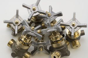
Know the Type of Pressure Control Valve You Need

No matter what project you plan to do, you need to know what type of valve is required to do it.

There are a vast number of pressure valves out there to choose from. To narrow the search down, it would help you to know the flow control type you need, the function the pressure valve will handle, and the operation it’s supposed to perform.

For example, some valves allow you to control or regulate flow (Shutoff & Needle Valves); while others are used in back- flow & water hammer prevention (Check & Stop-Check Valves). Others can be used for safety and pressure relieving purposes (Relief Valves); and still others are used for in-service calibration and pressure measurement (Instrument Valves).

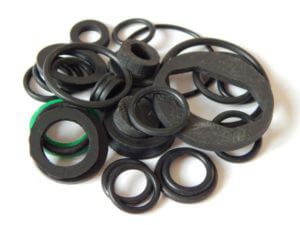
Know What Materials You Need out of Your Valve

Valves are constructed out of different materials, and you’ll want to know what materials are suitable for your project.

The media that flows through the pressure valve – be it gas (high purity, CO 2 , mixed gas, or flammable O 2 or H 2 ), liquid (water, oil, acids, food, chemicals), or plasma can affect the valve and reduce its performance if the wrong material is used.

There are a number of corrosive resistant valves made to handle harmful or caustic flow media, and other valves made from more standard materials for non-corrosive media, so make sure to choose wisely. Please contact us directly to ask our engineering team the best valve material to use for your application.

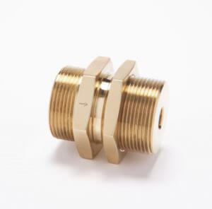
Know Your Valve Size

Finally, knowing your pressure valve size is important. Of course, if you don’t get the right size, you’ll most likely get a valve that doesn’t fit. However, there is more to it than that.

The size of your valve also correlates to the flow rate and capacity requirements of your piping system. For example, if a valve is too small it could throttle the flow of the media, making it harder to carry out the task.

An incorrect pressure valve size could also cause damage to the overall system, meaning you’ll have to shell out more money for repairs.

Knowing your valve size could help you avoid these problems and get your system working properly.

The Latest in Industry Standards

Now that you know what to look for in your pressure control valve, you need to know where to go in order to get the pressure valves you need at a price that works for you. Don’t worry: we’ve got you covered.

For many years, CPV Manufacturing has been a leader in quality manufacturing, and we make sure to give only the best to our customers. We offer a vast array of valves for you to choose from, as well as a long list of quality fittings.

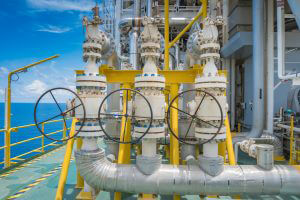
Our products are made to industrial standards and work to the standards of aerospace, shipbuilding, oil and gas, chlorine, petrochemical, and pharmaceutical sectors.

If you have any questions about who we are or what we do, please don’t hesitate to reach out. We’d be more than happy to answer any questions you may have. We look forward to helping support and provide assistance on your next project!

Preventing Seal Leaks

O-Rings: How a Small Part Plays a Huge Role

One of the attributes that determine the quality of a valve or fitting is its seal. A leak-proof control valve seal is not only desired but is an absolute necessity in many applications.

Leaking valves (or fittings), under the wrong circumstances, can allow toxic substances into the atmosphere or environment. Escaping oxidizers can lead to fire or explosion. And valuable products may go to waste.

Although it’s not the only factor involved, the O-ring is a crucial player in providing a no-leak high- (or low-) pressure control valve seal.

Since they were first patented in 1896 in Sweden by J.O. Lundberg, O-rings have become the standard in leak-proof design. (The U.S. patent was not issued until 40 years later to Niels Christensen.) The U.S. military created such a demand for them that the government took over the patent in order to have them manufactured by different companies for military aircraft use.

Jump forward another 15-20 years to the 1950s. CPV Manufacturing designed a full line of leak-proof valves and fittings using O-ring seals for the U.S. Navy.

Today, O-rings are the most sure-fire way to prevent seal leaks, and they are widely used across the world for leak-free valve and fittings.

Advantages of O-Rings

O-rings have a number of advantages over other types of seals.

Tight seal

Because they are almost all made of elastomers they can conform to hard surfaces to form a bubble-tight seal. When used correctly with a recessed close-tolerance groove, the internal system pressure (or external pressure) pushes the O-ring against the edge of the groove, forming a seal.

High pressure tolerance

Because of this O-ring face seal design, the bi-directional seal becomes tighter with increased pressure. The maximum pressure that an O-ring can withstand is dependent on the design of the system. Those with a smaller extrusion gap can handle higher pressures.

Make and break

The use of O-rings in valves and fittings allows for low-torqueing connections. There is no deformation of metal needed due to high torqueing requirements. They can be detached and reattached repeatedly without compromising the seal.

Ease of replacement

Use of O-rings in flat faced unions allows for versatility within the system that could never exist otherwise. CPV’s O-SEAL® line is the perfect example. Components can simply be lifted out and replaced with no cutting required.

Versatility in applications

O-rings come in almost any size and can be made of a number of different materials, which means there’s an O-ring for just about every application.

Material Selection

Choosing the right material for the intended use requires gathering some important information. Of critical importance when deciding on the right elastomer for a valve are:

Operating temperature

The temperature range at which an elastomer will retain its elasticity varies by material. For example, Viton® (fluorocarbon) can handle heat up to 400°F (204°C), but its low temperature limit is only -15°F (-26°C). Buna-N (nitrile), on the other hand, has a low temperature threshold of -65°F (-54°C) but a maximum of only 225°F (107°C).

Media composition

The elastomer can only be selected once the system fluid or gas is known. For example, oxidizers will degrade some materials while petroleum oils and/or fuels will damage others.

The extent to which the process chemicals will attack the elastomer is compounded by the operating temperature. The amount of damage will roughly double for every 18°F (10°C) of rising temperature.

Environmental conditions

Because the seal will be partially exposed to the external environment, those conditions also need to be taken into account. Outside temperature as well as pressure and chemical composition (for example, in an underwater valve) will all be in contact with, or will directly affect, the seal.

Common O-Ring Materials

Due to their tolerance levels for many of the chemical compounds that are used in industry, Viton®, Buna-N, and EPDM (ethylene propylene diene monomer rubber) are some of the most commonly used elastomers in O-ring seals. In general, these three are used as follows:

Buna-N

Good resistance to: petroleum-based oils and fuels, water, alcohols, and some acids and bases

Poor resistance to: strong oxidizers, acetone, and methyl ethyl ketone,

Viton®

Good resistance to: chemicals and oils (preferred for oil refining and chemical processing due to high temperature tolerance)

EPDM

Good resistance to: alcohol, acetone, solvents like methyl ethyl ketone, water, and steam

Poor resistance to: petroleum-based oils

Installation

Proper installation can mean the difference between a leak-proof seal and a disaster. Leakage can occur both around the seal and through it if not designed and installed correctly. Always follow the manufacturer’s installation instructions.

A few points worth emphasizing:

  • only use compatible lubricants when needed
  • never allow an O-ring to come into contact with any sharp edges or abrasive surfaces
  • always stretch the O-ring evenly and to within the specifications of the specific elastomer

Summary

O-rings made by our leak proof valve manufacturers and suppliers may appear to be just a small component of a valve or piping system, but they play a significant role in maintaining a leak-free process.

As leak proof valve manufacturers and suppliers, CPV’s O-SEAL® line of valves and fittings are the industry standard for no-leak, enduring performance. Take a look at our product lines or contact us to find out how we can help fill all of your valve and fitting needs.

The Check Valve’s Role

7 Tips for Using Check Valves in Steam Condensate Systems

Steam Condensate Systems

Many of our customers rely on the use of steam as a source of energy in their industrial chemical processes. While steam is ideal for powering countless industrial processes, the resulting condensate needs to be removed from the steam line as quickly as possible after its formation. Otherwise, lingering condensate can cause water hammer and other problems. Allowing it to pool inside the piping where a pressure drop could cause it to flash (the abrupt vaporization of a liquid). This can result in cavitation, erosion, excessive noise and valve failure.

Steam traps are constructed within the system in order to contain steam and remove the condensate as it is formed. When these two primary goals of a steam condensate system are done correctly, gravity will be your friend, and the condensate will flow downhill.

The Check Valve’s Role

Once removed, the condensate is usually captured and recycled back into the system. A properly selected and installed quick-closing check valve is essential in order to eliminate reverse flow and minimize the effects of flashing.

Check valves, which control the flow of fluid (gas or liquid) in one direction, are opened by the velocity of the forward-moving fluid. Depending on the type of check valve, they close when the flow slows, stops, or reverses, preventing the fluid from flowing in the reverse direction. Check this out if you’d like a run-down on the different types of check valves.

Of the various types of check valves, silent check valves are the ones we want to talk about when it comes to steam condensate systems. Silent check valves use a spring-loaded disc that closes when the flow velocity reaches zero and before it reverses. This eliminates the noise and vibration caused by swing check valves when the reverse flow slams them closed.

Consulting an expert when installing a steam trap is recommended, and it will help to eliminate any potential problems. Here are some tips for using check valves in steam condensate systems:

  1. Check valves should be installed to prevent backflow and siphoning of condensate from the return main equipment.
  2. Gravity rules. Condensate needs to be able to flow downhill from the process to the steam trap.
  3. Verify that the pressure ratings of the valves being used are sufficient for the pressure that will be produced by the system.
  4. Installing strainers that will collect any dirt or scale will extend the life of the check valves.
  5. An additional check valve may also be installed at the lowest temperature point of a system as a vacuum breaker if needed. When done correctly, it will open to the air rather than the return line within the system so as to not pull in any condensate.
  6. The check valve should be installed after the steam trap.
  7. Correct sizing of check valves is essential for steam service. Over-sizing increases the risk of erosion. It’s important to know the pressure, temperature and expected flow rate when sizing silent check valves for steam condensate systems.

CPV Silent Check Valves with their specially engineered stainless steel helical spring are the valve of choice for effectively controlling water hammer and other hazardous pressure surges. They’re perfect for condensate return lines with pressures up to 300 psi. The standard soft seats are perfect where a bubble-tight seal is required provided the temperature will not exceed 250°F (121°C). Metal-to-metal seats (stainless steel) are safe for use up to 350°F (177°C) and can be used if temperatures are expected to be higher. Check out our catalog for other options or contact us.

Method for Connecting Valves and Fittings

Connecting High-Pressure Fittings – When to Solder, Weld, or Braze

You’ve done your shopping and you have your high-pressure fittings. Now it’s time to put the system together. We sometimes hear the terms solder, weld, and braze used interchangeably (or even incorrectly). But these are unique processes. Each has its place in the industrial world. And not all methods are suitable for joining fittings used in high-pressure systems.

Selecting the correct method for connecting valves and fittings is based on the materials involved and their end use conditions such as service temperature, pressure, and needed corrosion resistance.

Choosing the Right Method

Soldering

Using a filler (solder) or flux to join two pieces of metal, soldering is a simple method that melts the solder but not the metals being connected. The two metals may be thin or thick and can be similar or not.

Soldering is done at relatively low temperatures and the solder typically melts anywhere between 361°F and 572°F (183°C to 300°C). A soldered bond is not nearly as strong as one that’s welded or brazed, and it would most definitely not hold up to high pressure. It does, however, fit the bill for some copper plumbing fittings.

In addition to not having high-pressure applications, it is not a good option where high-temperatures may occur or for connecting large pieces.

Welding

Welding can only be done using two similar metals. When welding, the parts themselves are actually melted and joined along the edges, although a filler metal may also be used to fill in or seal any gaps.

The welding temperature depends on the materials being welded. It has to be high enough to melt both of the metals in order to fuse them together.

Correctly done, the welded area is as strong as the adjacent metal, and welded seams can cover large areas. Overheating the metals can weaken them, so care must be taken to use the right temperature and not go overboard.

Welding isn’t a good option for thin metals. It can also result in localized distortion or internal stress of the welded area so consideration should be given to that possibility when it may affect fit or performance.

Brazing

Brazing joins two metals (including dissimilar materials) by bonding them to a filler. Unlike in welding, metals of different thicknesses can be connected via brazing.

By definition, brazing is done at temperatures greater than 840°F (450°C). In the real world, this temperature is usually over 1,000°F (540°C) and can range from between 1,000°F and 2,300°F (540°C and 1,250°C). The key to brazing temperature is that the filler must be melted, but the metals being joined need to remain solid. Some brazing methods heat the entire unit, eliminating or significantly reducing thermal stress and distortion.

Brazed metals get their strength as a result of a chemical reaction between the metals and the braze filler. Brazing forms an alloy creating a permanent bond that is at least as strong as the base materials. In fact, CPV’s Mark VIII O-Seal fittings, when properly brazed, may prove to be more durable than the tubing itself (as demonstrated by tests in the photos shown here).

Direct-Weld/Braze Fittings

In high-pressure systems where permanence is required, CPV’s line of low-cost Direct-Weld/Braze Fittings may be the solution.

Capable of handling up to 6,000 PSI (413 bar) of pressure, they are reliable when there is zero room for error.

3 Tips for Leak-Free Fitting Connections

Regardless of the method selected to attach your valves and fittings, you’ll want to follow a couple general rules to make sure they don’t spring any leaks:

  • The metal being joined must be properly cleaned ahead of time. Contaminants can interfere with the bonding and create gaps.
  • Be sure to use the right filler and flux for the application. A solder flux will not work for brazing and vice versa.
  • Make sure all parts are properly sized. This means knowing what method you’ll be using to connect them.

Whenever they’re available the manufacturer’s installation instructions should be followed. Information and step-by-step instructions for brazing your high-pressure CPV fittings can be found here.

You can trust CPV Manufacturing to have solutions for all your high-pressure fittings needs. Check out our full catalog or contact us to find out how we can help you.

Extreme Temperatures

Valves Below Zero

The high temperature extremes that occur in some processes or operations and the tolerance of certain metals to such heat tend to earn a lot of attention and respect. It’s got to be scorching hot before 316 stainless steel will melt (2507°F – 2552°F in case you were wondering).

At the other end of the spectrum, cold temperatures can wreak havoc on valves and fittings, too. The elastomers that comprise soft goods such as O-rings and discs may become brittle under frigid temperatures. The resulting inflexibility compromises the valve’s ability to seal.

Low temperatures should not be confused with cryogenic temperatures. Cryogenic environments range from a high temperature of -238°F (-150°C) to a low of -460°F (-273°C), also known as absolute zero.

When we talk about low temperatures in this article, we refer to the range between 32°F (0°C) and the low end of the ambient temperature scale – temperatures like one might find in northern regions of North America, Siberia, the Arctic and Antarctic. We are not referring to cryogenic temperatures.

Operations such as some oil and gas refining processes may take place in climates where the cold is unavoidable. Temperatures not only reach below freezing, but they can remain there for weeks on end. Standard valve models are rated for use down to 32°F.

Often times machinery and equipment in such locations is unattended and in remote areas where damaged valves and equipment are harder to get to for repairs.

What to Look For When Choosing Low-Temperature Valves

Material Selection

Selection of trim materials that will withstand low temperatures is crucial for reducing the risk of cold-related valve failure and/or malfunction. Two factors that affect the material’s cold tolerance are resiliency and periods of dormancy.

Resiliency – the ability of an item to return to its original shape after being stretched is known as resiliency. Resiliency declines as the temperature decreases. Under these conditions the valve’s disc, made of elastic polymers (a/k/a elastomers), will become hard or brittle, reducing its ability to form a proper seal and allowing for leakage. These elastomers also shrink under decreasing temperatures, further compromising the integrity of the seal.

Dormancy – in cases where a valve is not operated for long periods of time, such as when the cycling is long, the O-ring or seal may be in contact with the body for days or weeks. Long-term contact such as this can cause the seal to stick to the metal surfaces, no doubt affecting the valve’s performance.

The chart shown below shows the O-Ring and stem seal materials available from CPV Manufacturing and their corresponding temperature range. The standard, Viton, extends as low as -15°F (-26°C). Ethylene propylene (EPDM) ranges as low as -70°F (-57°C).

Low-Temperature Seal Materials

O-Ring & Stem Seal Temperature Ratings
Buna-N (Nitrile NBR) -30°F to +250°F (-34°C to 121°C)
Viton® (Fluorocarbon) -15°F to +400°F (-26°C to 205°C)
EPDM (Ethylene Propylene) -70°F to +250°F (-57°C to 121°C)
Polyurethane -40°F to +180°F (-40°C to 82°C)


It’s not only the trim materials that are subject to compromise in cold temperatures. The metal body has to be able to withstand the cold as well. Cast iron and some carbon steel alloys are not suited for cold temperatures beyond a certain range.

Quality Testing

Depending on the manufacturer, additional testing may be done to ensure quality and safety. Valves should always be tested to ensure that they meet at least the minimum safety and quality standards. These tests will include endurance, seat leakage, and external leakage. Always refer to industry regulations for required standards.

Manufacturers offering valves encompassing a lower temperature range do so using the newest technologies in valve manufacturing. Very few manufacturers offer these cold-temperature options.

You can trust that valves and fittings produced by CPV Manufacturing, with optional seal materials approved for temperatures as low as -70°F, are the highest quality and have met or exceeded all safety and quality standards.

Supplier Reliability

Low-temperature valves and fittings are not available from all manufacturers. In order to simplify inventory and ordering, and to ensure that worldwide industry standards and regulations are met, companies may choose to stick with one source and possibly one specific material for all their valves or for a particular application. They may use the same valves across the board, regardless of location and temperature.

When low-temperature valves and fittings are needed, be sure to consider the reliability of the materials as well as the reliability and reputation of the manufacturer. You want to be able to get the valves and fittings that you need quickly. It’s equally important to have access to customer support.

Questions about CPV’s low-temperature or other valves? Contact us.

Sizing a Valve

Selecting the Right Control Valve

Sizing a control valve may seem like a no-brainer (how tough can it be?), but it’s actually quite the opposite. The selection process goes way beyond just looking at the size of the pipes. The gas or fluid (and its viscosity), pressure and pressure differential, as well as the flow rate and required flow characteristic all must be factored into the decision…and that’s just to determine the size.

The last thing anyone wants is for a valve to fail prematurely or unexpectedly. Some of the most common causes of failure are damage from:

  • Cavitation
  • Flashing
  • Erosion
  • Vibration
  • Corrosion

One way to reduce the likelihood of failure is to be sure to select the right size, style or type, and body and trim material up front.

Consequences of Using the Wrong Size Control Valve

A valve that’s incorrectly sized can lead to problems:

  • If it’s too small
    • It cannot handle the flow that it needs to.
  • If it’s too large
    • It cannot be adjusted to the required flow rate with any relative precision. Changing the valve’s position just slightly will create big, non-proportional changes in the fluid’s flow…it becomes overly sensitive.
    • The valve’s precision will be further reduced by any friction in the system (which will cause stickiness).
    • To top it off, purchasing a larger valve will cost more than it needs to.

Tips for Determining the Right Size Valve

According to Control Valve Primer – A User’s Guide, some recommendations to help guide you to the right control valve are:

  • An equal percentage valve works well for a system with a lot of pipe.
  • Linear valves work better for systems with a small amount of pipe.
  • Standard practice is to use a control valve that’s no larger than the line.
  • Never install a valve on a pipe that’s more than twice the diameter of the valve.
  • Globe valves are commonly one size smaller than the line. If you get a different result, you may wish to double check your information.
  • You’ll achieve the best control with a valve that’s sized to operate at:
    • 60 to 80 percent open at the maximum required flow and
    • around 20 percent open at the minimum required flow.

Other Factors Affecting Valve Size Selection

Flashing and cavitation

Any time there is risk of flashing and cavitation it can and should be factored into the sizing calculations and selection criteria. Cavitation creates noise and vibration and can cause a lot of damage to the internal parts of a valve and the pipes downstream.

In rotary valves predicting the level of cavitation that will cause damage requires more than a simple calculation. Localized areas of pressure drop followed by recovery may cause cavitation way below the threshold that causes the flow to be fully choked.

Choked flow

With flashing and cavitation comes the added problem of choking. Flashing, or the formation of vapor bubbles just past the vena contracta, limits or chokes the flow through the valve. If the downstream pressure drops past the point of flashing, the flow will become choked.

The basic liquid valve sizing equation must be modified based on this pressure differential and using a valve recovery coefficient.

Separate calculations are needed to determine the pressure at which cavitation will occur and choked flow will begin.

Viscosity

When dealing with the added friction of a highly viscous liquid, the valve sizing coefficient needs to be increased. Viscosity is only an issue when it exceeds 40 centistokes or when the valves are to be very small with a valve sizing coefficient of less than 0.1.

When either of these situations exists, additional factors and calculations have to be figured into the equation.

Noise

High noise levels cause vibration which may damage pipes as well as other equipment. Noise levels are even more likely to exceed standards in steam and gas service (even when the pressure drop isn’t extreme), especially as the valve and pipe size increases.

Noise should be considered in the calculations for selecting and sizing control valves, particularly for oil and gas service.

 Flow Characteristic

The flow characteristic, or the relationship between the valve stem travel and the flow through the valve, typically should be linear (when plotted on a chart). The inherent flow characteristic (which comes from the manufacturer) usually changes once put into operation. Things such as drops in pressure choked flow (flashing and cavitation), and location of the valve within the system will have an impact on the flow characteristic.

The actual flow once installed, referred to as the installed flow characteristic, will be hard to control if it has strayed too far from a linear flow.

Computer Analysis to Determine Control Valve Size

All this being said, it is important and useful to understand the how and why of valve selection, but to fully cover the sizing of control valves requires a small textbook or at the least, a large user manual.

For those of us who love performing calculations, we can run through pages upon pages to work out the best solution.

For everyone else (and even for the former to verify our conclusions), a software program will do the heavy lifting for you and is recommended.

Avoid potentially costly mistakes by doing your homework (on a computer) the first time around.

Just in case you really wanted some math…

The following formula applies to about 80 percent of liquid sizing applications. Gas or steam valve sizing requires a different formula.

q = Cv √ΔP/Gf

Where:            Cv = valve sizing coefficient

q = the flow rate in U.S. gallons per minute

                        ΔP = change in pressure – inlet minus outlet pressure in psi

Gf = specific gravity of a liquid at a given temperature

Remember: the calculation will need to be adjusted when more viscous fluids are processed or when cavitation or choking is expected.

Selecting the Type of Control Valve

There’s less calculating needed to determine the type of control valve to use, but the decision still requires some thought. The same criteria for valve selection that we’ve talked about in the past apply to control valves: the liquid or medium, pressure and pressure differential, operating temperature, environmental conditions, cavitation risk, and flow characteristic.

CPV Manufacturing’s control valves are available in a range of options for all of these criteria including temperature, pressure, and flow characteristic. O-SEAL®, G-Series®, Mark VIII®, and FloMaster® Valves are all available to fill your control valve requirements. The tapered plug in our needle valves provides a large flow area and superior flow control. Our leak-proof designs are trusted worldwide and always exceed quality standards.


Take the time, in the beginning, to ensure you install the right valve for the job. For help or questions regarding any of CPV’s products, contact us.

I

Discover the Differences Between Actuators

Choosing an Actuator—Where to Start

What makes a valve a valve is its ability to control flow. It stops it, allows it, or holds it somewhere in between.

The mechanism that makes this happen is the actuator. Simply put, the actuator opens and closes the valve.

But there’s a bit more to it than just that…

  • First, it has to be able to move the valve closure member (ball, disc, or plug). It must have enough torque (for quarter-­turn) or thrust (for linear) to be able to move it regardless of conditions.
  • The actuator must hold the valve open or closed (or at a specific position between the two) against the forces trying to move it. This includes holding up to dynamic torque conditions where necessary.
  • It needs to have a system failure mode or position. Depending on the circumstances, failure may require the valve remain open, closed, or again at a designated position somewhere in between.
  • For partial-­turn valves, the actuator must have the ability to rotate it to the degree required (90°, 180°, etc.). When rotation greater than 180° is needed, electric actuators are the more popular choice.
  • It has to be able to operate at the required duty cycle and speed. When considering an electric actuator, special attention should be paid to the maximum speed required.

Types of Actuators

 Here’s a quick rundown of the basic types of actuators based on how they are powered:

Manual actuators require someone to physically move them by turning a hand wheel or switching a gear or a lever. The wheel can be attached directly to the valve stem or will sometimes use gears to make turning the wheel easier. Manual actuators are the simplest and least expensive option. There are, however, many instances where they are either not practical or not safe. They may be too large to be able to turn by hand or they might be inaccessible due to their being in hazardous or hard-­‐to-­‐reach locations.

Pneumatic actuators use air pressure (compressed air) to move a diaphragm or piston which in turn moves the valve stem. They are useful when modulating or throttling the fluid is necessary. Pneumatic actuators can be used for linear or quarter-­‐turn valves.

Hydraulic actuators use fluid pressure instead of air pressure. Like pneumatic actuators, they are used for linear or quarter-­‐turn valves. The addition of a spring makes them a good choice where a fail-­safe mechanism is needed. Unlike pneumatic actuators, they can be used on one or both sides of a piston when valves need to be moved both ways.

When more force is needed, hydraulic actuators have a huge advantage over their pneumatic cousins…they can produce 25 times the force of pneumatic valves.

Electric actuators are powered by an electric motor and are connected to the valve stem by way of gears. Hand wheels or backup power can be added in the event of power failure.

Solenoid actuators use a magnetic slug. The slug (attached to the valve stem) is drawn to an electromagnetic coil in the actuator. They can also be positioned manually.

Self-­‐actuated valves are those that are moved into position by the movement of the fluid in the system. Safety, relief, and check valves are self-­‐actuated.

Comparison of Characteristics—Pneumatic vs. Electric

 Two of the most commonly used types of automated actuators are pneumatic (like CPV’s FloMaster of pneumatic control valves) and electric. Some of the considerations when making a choice between the two are as follows:

Power Supply

The first step in deciding whether to use a pneumatic or electric actuator is to look at the power source.

Pneumatic actuators need to have an air pressure supply of 40 to 120 psi…CPV FloMaster Valves need less than 100 psi.

Electric actuators require a 115 VAC power supply. In some cases, AC or DC motors of different sizes may be used.

Temperature

Standard pneumatic actuators can operate in ‐4 to 174°F. That can be stretched to ­‐40 to 250°F by simply using the right seals, bearings, and grease. CPV FloMaster Valves have a temperature range of 20 to 225°F. Note that cold temperatures bring the risk of freezing condensation which can block air supply lines leading to failure.

Electric actuators operate between -­40 to 150°F. Care should be taken to shield electric actuators from the elements if they’re used outdoors. It’s possible for condensation to form due to temperature fluctuations and moisture. A heater should be used wherever there’s risk of condensation to help alleviate this problem.

Hazardous areas

Electric actuators may be needed in a hazardous area. When used in hazardous areas the electric actuator must have the proper enclosure for containing an internal explosion without causing external damage following the National Electrical Manufacturers Association (NEMA) Type 7 guidelines for electric devices. Many manufacturers have a version of their products that conform to these guidelines.

Pneumatic actuators, on the other hand, can be used in hazardous areas without concern for fire or explosion risk. They are the safer option. Using electric controls with pneumatic actuators is a cost-effective way of dealing with such situations.

Spring Return

Required in most industries, the spring return actuator returns the valve to a safe position in the event that it doesn’t receive a signal due to power loss or other problem. It’s a cost-­effective solution with pneumatic actuators. In the case where springs won’t work due to size or weight of the actuator, an accumulator tank can be used to store air pressure.

Electric actuators can be equipped with a battery backup in lieu of a spring return, which isn’t as available.

Duty Cycle

The harder pneumatic actuators work, the better they work. They have a 100 percent duty cycle which means they can run constantly.

Most electric actuators have a 25 percent duty cycle…for every 1 minute of cycle time, they need 3 minutes of rest. They will overheat if they are run continuously. This isn’t usually a concern since most on-­‐off automated valves are idle about 95 percent of the time. If it’s necessary, electric actuators can be upgraded to as much as 100 percent by using capacitors and optional motors.

Speed Control

Controlling the speed of pneumatic actuators is not difficult, assuming the supply and exhaust lines are correctly sized. Fitting it with a needle valve at the air pilot exhaust port is the simplest way to control speed.

Electric actuators, on the other hand, can be adjusted to operate more slowly. But overall, speed control in electric actuators is much more challenging. The speed is based on the power of the motor.

Sizing

Whether pneumatic or electric, selecting the right size actuator is a complicated process. It’s based on the required torque, the minimum and maximum supply pressure, the type of actuator, the failure mode requirements, and the characteristics of the valve and media. Using an undersized or oversized actuator can lead to failure. Always consult a trained expert for sizing actuators.

It’s always important to have the right tools for the right job…that applies to valves, fittings, and actuators just as much as it does to drill bits and Allen wrenches. Our trained valve experts are happy to help with any questions you might have.


Valves Used in Numerous Industries

The Many Places You’ll Find Valves

Anywhere that a fluid or gas flows through a pipe, you’ll find valves. They regulate flow, stop it, and start it again. Safety and relief valves protect property and lives from over pressurization.

CPV Manufacturing’s high-quality valves are used in some of the toughest industries and harshest environments on Earth. Here are a few of the places you might find them:

Marine & Shipbuilding

Ships are complex. From fuel distribution and storage to cargo loading and unloading, the ballast and bilge systems, refrigeration, and hydraulic systems, there’s no shortage of valves on a ship. You’ll find all types, from metal-seated ball and butterfly valves to relief, check, gate, and globe valves.

Large ships havecomplex systems of pipes and valves to direct the fuel. US Navy aircraft carriers use CPV valves in the lifting of aircraft to the flight deck and in bringing the jets to an abrupt halt when they land.

Marine settings are some of the most hostile…even fresh water is damaging to pipe and valve systems. Plain water causes oxidation to susceptible materials. In seawater, oxidation is compounded not only by the effects of salt, but the sand and mud, plant particles, microorganisms, and small animals. Certain bacteria can produce hydrogen sulfide, ahighly corrosive toxic gas. Valves used in naval settings have to be able to stand up to the inhospitable aquatic environment.

Oil and Gas

Oil and gas production requires heavy-duty valves and pipes. From offshore oilrigs to onshore processing and distribution, a multitude of valves will be found along the way.

Offshore rigs and facilities

Offshore oil rigs have several different functions, each requiring pipe and valve systems of their own. Piping the oil or gas from the land beneath the water requires valves and equipment that can work under as much as 10,000 feet of water.

The Christmas tree valve assemblies that can be seen on top of wellheads are a combination of valves including gate valves and chokes. Their primary function is to control the flow out of the well. Christmas trees are made to handle up to 10,000 psi of pressure and can be found both on land and in offshore wells.

Once the oil has been extracted, typically the water will be removed from the hydrocarbons, and natural gas liquids will be separated from the fluid stream. Sometimes sour gas, raw petroleum containing hydrogen sulfide, is present. Due to its highly corrosive, flammable, and toxic nature, special handling is required including the use of corrosion-resistant valve materials.

The valve that you’ll see the most on an oil rig is the ball valve, although other types of valves are also used.

The American Petroleum Institute (API) as well as the American Society of Mechanical Engineers and NACE (formerly the National Association of Corrosion Engineers) have standards and recommended practices that are to be followed depending on the circumstances. Specifications that may apply on an oil rig are: NACE MR0175, API 594, API 600, API 602, API 608, and API 609, API 6D, API 6A.

Pipelines

The underground pipelines that transport petroleum have valves spaced at intervals, specified by codes and laws, for their entire length. If there were to be a leak, these emergency shutoff valves would be closed, minimizing potential hazards, loss, and environmental damage. Shutoff valves also allow for maintenance to be performed.

Underground pipelines also have stations where they come above ground to allow for cleaning or inspection. The valves at these stations must be able to be fully opened so that the cleaning and inspection equipment can be fit through. Gate or ball valves are typically used at these stations.

Pumping stations containing gate, ball, and check valves are located along the length of the pipeline in order to keep the fluid moving.

The American Petroleum Institute specifications API 6D apply specifically to pipeline valves.

Refinery and petrochemical

If you’d like to see an example of almost every type of valve, a large refinery is the place to be. High temperatures and corrosive fluids are common in refineries. Such valves require extra resistance, which can be accomplished with the use of thicker walls and the right materials using metals ranging from carbon steel to high-nickel alloys.

Specifications API 594, API 600, and API 608 may apply to the valves used in a refinery.

Liquefied Natural Gas

Liquefied natural gas is about 600 times smaller in volume than in its gaseous state. Achieving this liquid state requires that it reach a temperature of -265 degrees F. The pipes and valves used in this process are large, so they must handle high pressure as well as the very low temperatures needed for liquefaction. Popular valve types in LNG production are quarter-turn ball and butterfly valves.

No valve packing materials, however, can withstand such low cryogenic temperatures. To work around this factor, a gas column is used. This column keeps the packing away from the cryogenic conditions so that it doesn’t freeze which would immobilize it.

Gas Separation

Like LNG, gas separation also occurs at very low temperatures. The valves used for gas separation must be tolerant of very low temperatures.

As in LNG production, a gas column is used to separate the packing from the low-temperatures needed for gas separation.

Chemical

The 316/316L grade of austenitic stainless steel is the metal of choice where corrosion is of moderate consideration. Production of highly corrosive chemicals requires the use of even more heavy-duty metals and alloys.

Chemical production is usually done at lower pressures than in the industries discussed above, so pressure is less of a factor than it is with others.

Linear valves are still used for some chemical processes, but the resilient-seated ball valve is popular for many chemical applications due to its zero-leakage shutoff and compact size. Diaphragm, pinch valves, gate and globe valves are used as well.

This is just a sampling of all the places valves are used. Even if you’re not directly involved in one of the industries we serve, there’s a pretty good chance that your daily life has been touched in some way by a CPV valve.

The Importance of the Right Trim

For Optimal Performance, Choose the Right Trim

When shopping for a new car, most of us look for something that will serve our needs while offering the best performance. It should be the right size and shape (SUV, van, compact), have the right options (engine size, sound system, tires), and be able to hold up to whatever abuse we dish out (dirty feet or paws, spilled coffee or juice). We also know going into it that it will require regular maintenance (oil and fluid changes), and some parts will need to be replaced from time to time (belts and tires).

When selecting the right valve, the same general ideas apply. To have optimal performance, it has to be the right size and shape, have the right options or parts (whether it’s a ball, gate, or butterfly valve, check valve or pressure relief valve), and be able to tolerate the conditions of use (temperature, pressure, and the chemical nature of the fluid). And just like a car, valves require regular maintenance with some parts occasionally needing to be replaced due to wear from regular use.

Recently we shared an article about choices in materials that comprise valve bodies and trim. (If you missed that, you can read it here http://www.cpvmfg.com/blog/valve-materials-many/ ). But trim is unique. Trim warrants an article all to itself.

The internal, replaceable parts of a valve…the trim…need to perform without fail. They are the moving parts that make a valve a valve.

What you need to know

If you’ve ever gone through the process of selecting a valve, you know it’s not exactly like browsing through a catalog. For optimal performance, you’ll need to have the following information to make the best decision:

  1. The fluid — the first thing you must know is what will be flowing through the valve. If it contains fibrous particles or solids, valves that obstruct the flow (such as a butterfly valve) should be avoided. Not only are solids and particles erosive, but they may clog the opening. On the other hand, viscous fluids can create drops in pressure. Butterfly or ball valves are good options for viscous media.
  2. The valve size — at first it may seem like the size of the valve has nothing to do with the trim. But an oversized control valve would have to be operated with a low or narrow opening, making it unreliable and causing the valve seat and closure to sustain more erosion damage.
  3. The valve pressure drop (ΔP) — the difference between the upstream and downstream pressure of the valve is important for two reasons. First, a large pressure drop puts stress on the valve stem, so it must be strong enough to withstand it.

Second, high-pressure drops lead to flashing and cavitation, which can be very damaging. Flashing occurs when the pressure within the restricted flow area of a valve drops below the vapor pressure of the liquid resulting in vaporization. The vaporized liquid releases a lot of energy, moving the remaining liquid particles at a high velocity and causing damage to the internal components of the valve.

Cavitation occurs when the pressure changes that led to flashing begin to return to normal. With cavitation, vapor bubbles collapse or implode, resulting in a release of energy or a shock wave. In a closed system, when there is no escape for that energy, the internal valve surfaces and components are gradually worn down becoming brittle and susceptible to breaking or fracturing. Cavitation produces a grainy appearance.

  1. The fluid — the first thing you must know is what will be flowing through the valve. If it contains fibrous particles or solids, valves that obstruct the flow (such as a butterfly valve) should be avoided. Not only are solids and particles erosive, but they may clog the opening. On the other hand, viscous fluids can create drops in pressure. Butterfly or ball valves are good options for viscous media.
  2. The valve size — at first it may seem like the size of the valve has nothing to do with the trim. But an oversized control valve would have to be operated with a low or narrow opening, making it unreliable and causing the valve seat and closure to sustain more erosion damage.
  3. The valve pressure drop (ΔP) — the difference between the upstream and downstream pressure of the valve is important for two reasons. First, a large pressure drop puts stress on the valve stem, so it must be strong enough to withstand it.

Where sulfide stress cracking is a factor for oil and gas companies, ANSI/NACE MR0175/ISO 15156 should be consulted for material guidelines.

Trim materials

The list of possible materials for trim construction is extensive. Some of the most popular options for each part are listed here.

The stem is connected to the disc, which is what opens and closes the valve. The valve stem has to be able to withstand the force needed to move the disc, so it has to be very strong, but also resistant to corrosion and erosion. Metal alloys are usually a good choice for the stem.

The valve packing is the gasket that seals up where the stem and body meet. Packing is frequently made of graphite or Teflon (it’s not just for frying eggs). Graphite can endure temperatures up to around 1500 degrees F. Teflon doesn’t create much friction, so it’s slippery; however, its maximum temperature is only about 500 degrees F. There are a few different Teflon compounds, so temperature tolerance does vary.

The disc is crucial in determining the valve’s performance and seal. Discs are commonly made of reinforced forged steel.

The seat connects with the disc to form the seal that’s responsible for stopping the flow. Seats and seals can be soft or hard. The seating material in most soft-seated ball valves is usually Teflon. In order to increase its strength, high-temperature tolerance, and corrosion/erosion resistance, it’s sometimes combined with graphite or glass powder. Stellite is a popular erosion-resistant alloy that is also used in seating surfaces where high temperature is a factor. Stellite is corrosion resistant and extremely hard.

Industry-specific guidelines

All of our products at CPV are manufactured to meet industry quality standards. The American Petroleum Institute (API) has arranged numbered groupings of trim components for the oil and gas industry to guide them through the selection process. NACE (formerly the National Association of Corrosion Engineers), the American Society of Mechanical Engineers (AMSE), and the American National Standards Institute (ANSI) all have recommendations or standards for valves as well.

At CPV Manufacturing, we take pride in helping our customers make the best valve and trim choices for their project…quality over quantity.

Valve Materials: Do There Have to Be So Many?

When it comes to choosing the right valves for your project, there’s a lot to consider. Valves serve many purposes and industries. And within each industry, they have numerous different functions. So while all CPV valves are manufactured to meet or exceed the highest quality standards, they’re not all the same.

Several factors come into play when making a decision about which valve will meet the requirements of the job for which they’re needed. Besides knowing the function or the action it will perform, it’s necessary to know the type of fluid or medium that it will be used for, the temperature of the substance, the pressure and flow rate, and the size of pipes or other equipment it will be connected to.

Armed with this information, you’ll be able to narrow down the options and select the product that will best suit your needs and provide the most return on investment.

One of the most important decisions you’ll make during this process is selecting the materials for the valve body and trim. Valves can be composed of materials ranging from cast iron to bronze to PVC. In valves like the ones CPV manufactures, there are typically two or more different metals in a single valve.

You may wonder why we don’t always use the “best” material for everything. It doesn’t quite work that way.

What’s best for one application might be the worst possible choice for another. And the “best” might not be the most cost-effective.

Factors Affecting Body Material Selection

 Once you know what type of valve you need, the next step is to determine what metal or material will best suit the application.

Let’s look at some factors that will help guide this decision.

Resistance to Corrosion

Corrosion is the act of destroying, weakening, or wearing away a surface. It affects both the exterior and the interior of the valve.

In the external environment, air and moisture can lead to corrosion. In materials such as iron and steel, we see this in the form of rust. Many CPV customers have more than just the usual air and humidity to consider. Their businesses may operate in or near salt water. The harsh external environments to which their equipment is subjected accelerates the rate of corrosion. If you’ve ever owned a vehicle and lived near the sea or in a cold climate where the roads are frequently covered with salt to melt snow and ice, you know that when salt combines with water and air, rust appears even faster on an automobile’s steel parts.

But exterior corrosion in the form of rust isn’t the only concern. When a substance is flowing through a valve, corrosion can occur from the inside as well. The rate and degree of internal corrosion are dictated by the type of substance flowing through the valve. Sweet crude oil for example (crude oil containing low amounts of sulfur), is non­‐corrosive and actually helps to protect the metal surfaces it contacts. Strong acids like sulfuric acid, on the other hand, can eat through some metals in a matter of hours.

Strength of the Material

There are two general measures of strength that play a role in valve material selection. Tensile strength is its stretchability or resistance to breaking when it’s stretched. If it can be stretched a little without breaking, it’s ductile. Copper is an example of a metal with good ductility, which allows it to be stretched into a wire. If a material doesn’t stretch, it’s brittle, like a ceramic plate that shatters rather than bends when it collides with a hard surface.

A valve’s body has to be able to withstand the pressure from inside. That’s where its tensile strength comes into play. A metal such as cast iron may seem like a good choice, but it’s brittle and cracks under too much pressure. In operations where high pressure is a factor, the material used must have good ductility. Knowing the pressure during operation is essential in selecting the right valve material.

Operating temperature also affects a metal’s strength and is another important factor in determining its suitability for a valve. In general, as the temperature increases, the metal softens and weakens. If it’s too cold, the wrong metal becomes brittle. So the temperature limits of the valve material must be aligned with the temperature at which it will be operated.

For example, a low-­‐grade carbon steel can handle 285 psi at 100 degrees F, but that number drops to merely 50 psi at a temperature of 900 degrees F. Long exposure to high temperatures can also change some carbon steels to graphite. Depending on the particular metal, the tolerance range, as in the case of cast iron, may be as limited as ­‐20 to 410 degrees F. On the opposite end of the spectrum, certain stainless steel alloys have a broad range, from as low as ­‐425°F to as high as 1500°F.

Resistance to Erosion

With each component of a valve serving a unique function; and therefore being subjected to somewhat different conditions, special materials are usually required for a valve’s trim (the closure elements or parts such as the stem, seat, and disc). In addition to strength and corrosion resistance, the trim is more susceptible to erosion.

Similar to corrosion, erosion is wear caused by a mechanical action or the repeated application of localized stress. In other words, a substance breaking down a solid material due to pressure and repeated action, rather than a chemical reaction.

Sandblasting is a form of erosion. Dirt or other abrasive particles contained in a substance will contribute to metal erosion.

The effects of erosion are amplified on trim closure elements. As a valve closes, the velocity of the substance flowing through it increases, like putting your thumb over the end of a running water hose to make the water spray out with more pressure. This increased velocity causes wear in the form of erosion.

CPV Manufacturing is committed to making only the best quality valves and fittings. We design them with versatility in mind so that our products are perfect for many industries, purposes, and settings including the harshest of environments. Whatever your needs, you can trust CPV to provide the highest quality products to satisfy them.