Valves 101: The Ultimate Guide to Valves
With more and more advanced technologies being developed every day, it’s easy to forget that valves are still one of the most critical components in industrial plants. In fact, without the proper valves, systems are more to likely deteriorate and ultimately fail.
To prevent these catastrophic system failures, here’s your ultimate guide to valves to help you get a better understanding of some of the most important devices in your plant.
Basic Valve Information and Uses
Valves are mechanical devices used to regulate and control the flow of an industrial system or process. This means they can stop, start, or throttle flow. They can also increase or decrease the amount of pressure flowing through the system.
Valves are designed to work with a variety of materials as well. This includes liquids, gasses, vapors, and even corrosive materials. Because of their versatility, most valves are ideal for an array of industries, including the manufacturing industry, the petrochemical industry, and the compressed gas industry.
Types of Valves
However, not all valves are the same. Many different types of valves are designed to work with specific materials and provide a particular function. To help you understand which valve is right for you, here’s a breakdown of a few of the most common valves for industrial systems.
 Pressure Relief Valves
Pressure relief valves prevent overpressure situations for high-pressure systems. They’re designed to gradually open depending on the system’s current pressure levels. When pressure increases, the valve opens more so more fluid can flow through. This helps to maintain appropriate pressure levels and ensures stable and safe operations.
- Globe Valves
Globe valves start, stop, and throttle the flow of the pipeline. The disc in the globe valve moves slowly from the seat to prevent vibrations and water hammer. Generally, companies use this valve as a regulating device and an on/off device.
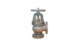
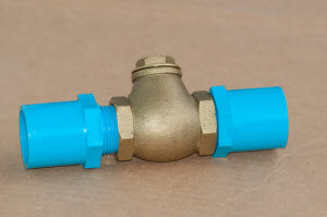
- Check Valves
Check valves help systems to maintain flow in one direction. This two-port device uses a clapper that lifts to keep fluids flowing in the right direction. When pressure in the system begins to decrease or when the flow starts to reverse, the flapper closes the valve to ensure proper directional flow.
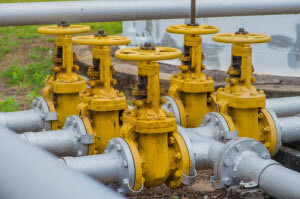
- Gate Valves
 Gate valves are designed to be on/off valves for industrial companies. They won’t regulate the flow or pressure within a system, but they’re known to have lower pressure drops when correctly installed.
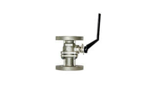
- Ball Valves
Ball valves use a rotating ball to open and close so they can transfer various types of materials through a system. They’re known to be fast-acting valves, which makes them ideal for any start/stop application.
Materials and Selection
All valves are made with different types of materials. Depending on the application, you’ll need a valve made of a specific material to ensure proper operation. For example, if you’re looking for something that can withstand corrosion, you’ll need to choose a valve made of nickel alloys or other durable metals.
To ensure that you select the right valve for your system, consider the application and the type of liquid or gas through the system. This will help you understand what type of valve you need as well as which material will work best for your needs.
Valves are essential parts of any industrial system. If you’re looking for a high-quality valve for your company, check out CPV Manufacturing’s catalog of pressure relief, check, and gate valves. As a leading valve manufacturing company, CPV can provide you with the necessary insight to purchase the right products for your projects.
 Globe valves designed to have the pressure flowing under the disc are used in low-pressure and low-temperature applications such as general plumbing. This type of flow direction lets the disc to rotate freely on the valve stem. This allows the disc to fit properly against the seat as the valve closes, which results in less seat leakage
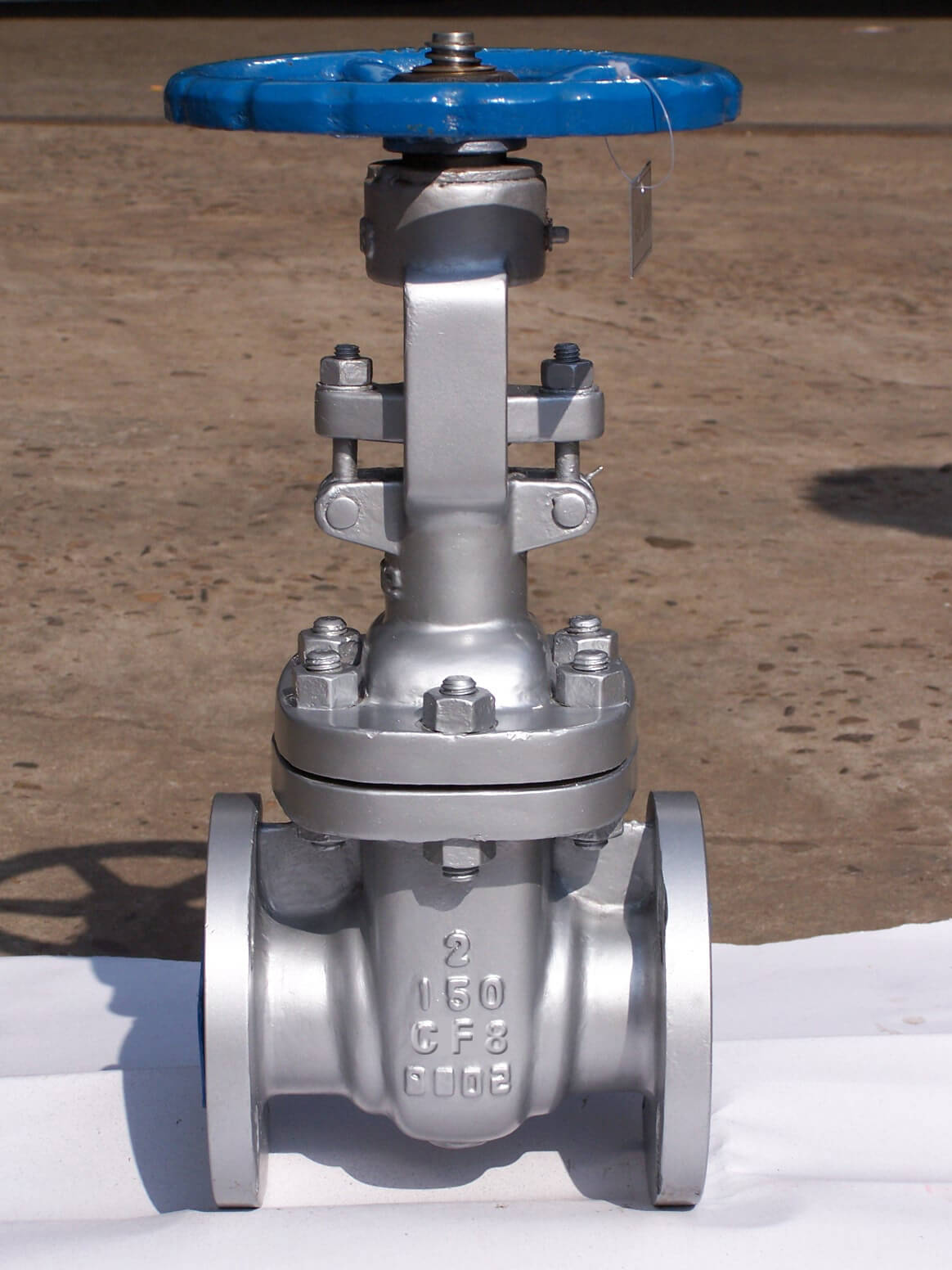 Globe valves vs gate valves are designed for many applications in several fields, including the oil and gas industry. However, each valve doesn’t serve the same function.
 To help you train your new team of workers, here are a few tips to ensure proper training for valve and control engineers in your plant.
 Industry 4.0
 Water hammer is a common problem with various types of systems and pipelines. It’s caused by pressure surges and shock waves that occur when the direction and flowrate of the liquid running through the system changes. Symptoms of water hammer include loud hammer noises and vibrations in the pipelines.
 Like water hammer, reverse flow can be prevented by using a
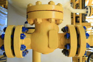
 Check valves are one of the most-used valves available and for good reason. These valves can help to boost efficiency and ensure safety for many types of systems.
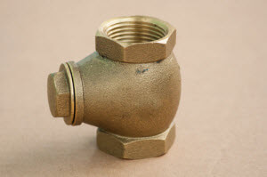 Swing check valves feature a simple design complete with a disc attached to a hinge at the top. As fluid passes through, the valve remains open. When a reverse flow occurs, the changes in motion as well as gravity help to bring down the disc, effectively closing the valve.
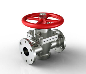 These types of check valves also work with an external mechanism or an override control. With these, you can set the valve to close regardless of flow direction or pressure to ensure safety and efficient operations.
 Hydraulic systems are made up of numerous parts:
 In addition to vehicles and industrial machinery, hydraulic systems can be found on ships. Hydraulic systems on ships are used in various applications. For example, systems used for cargo systems make carrying heavy materials and performing other cargo operations easier and less time consuming.
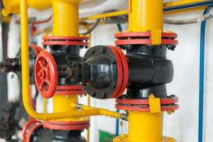 Control valves are one of the leading factors in plant efficiency. They’re designed to keep systems operating smoothly and safely. However, with time, a valve’s performance can plunge. Luckily, there are ways to prevent that and optimize its performance.
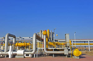 For a control valve to work properly, the linkage within the assembly must provide feedback on the valves’ position so the control instrument can control it accurately. Unfortunately, vibrations that occur around the assembly can cause damage and severe wear and tear to the linkage. This can make it fail in providing the necessary feedback.
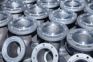 Forging and casting are two of the most common ways to create
  Unlike forging, casting uses the liquid form of metal to create valves. These metals are melted into a molten liquid and poured into various molds. Once the liquid cools and solidifies, it’s broken out of or ejected from the mold.