Preventing Check Valve Failure – Best Practices

Check valves play the role of unsung hero, silently managing the unidirectional movement of substances and thwarting the menace of backflow. Check valves are found within the intricate web of industrial processes, where fluid and gas flow dictate the rhythm of operations. Yet despite its straightforward function, a check valve failure can unleash a cascade of consequences, from compromising system integrity to costly equipment damage.

Recognizing the pivotal role of check valves to maintain operational efficiency, process engineers can follow best industry practices to avoid check valve failure. This blog discusses how to recognize the purpose of check valves, identify symptoms of malfunction and explore underlying causes of failure.

What is the function of a check valve?

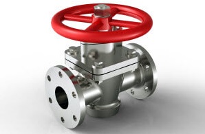
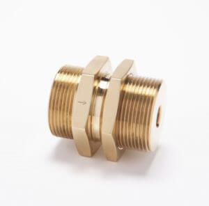
A check valve employs a straightforward yet effective mechanism to restrict flow within piping and equipment to a single direction. Typically, a check valve consists of a hinged or spring-loaded disc in the body. When gas or fluid flows in the desired direction, the pressure of the incoming flow pushes against the disc, causing it to open or move away from its seat, allowing the fluid to pass through the valve. This forward movement must be of a sufficient pressure to overcome the resistance of the spring and the weight of the disc.

However, in the event of reverse flow, the pressure differential causes the disc to close against the seat, preventing backflow. Stainless steel, brass, or bronze often serve as preferred materials for check valve fabrication. An O-ring helps seal the seat, and springs are used to aid with secure closure. This design serves to enhance the valve’s functionality and reliability for establishing one-directional flow and preventing backflow.

Many industries and processes rely on check valves including:

  • Chemical processing
  • Oil and Gas / Refining
  • Industrial Gas
  • Waste and wastewater treatment facilities
  • Power generation
  • Marine and shipbuilding
  • Food and beverage
  • Commercial HVAC and plumbing

What are the symptoms of a bad check valve?

  1. Leakage: One of the most common symptoms of a bad check valve is leakage, which can manifest as loss of pressure within the system or external leakage around the valve itself. This leakage may lead to inefficiencies in system operation and even potential safety hazards.
  2. Pressure Fluctuations: A malfunctioning check valve can result in deviations from normal operating pressure within the system. These fluctuations may indicate improper sealing or flow reversal, compromising system performance and stability.
  3. Visual Indicators: Corrosion, rust or debris accumulation on the exterior of the check valve can serve as visual indicators of potential internal issues. These signs suggest deterioration or damage to the valve components, affecting its functionality and reliability.
  4. Condensation or Wetness: Presence of condensation or wetness around the check valve may indicate leakage or improper sealing, leading to fluid bypass and potential system inefficiencies.
  5. Inconsistent Operation: Changes in the way the check valve operates, such as failure to open or close properly, can be indicative of internal damage or wear. These inconsistencies may disrupt fluid flow and compromise system integrity.

By recognizing these symptoms, operators can identify potential issues with check valves and take appropriate measures such as inspection, maintenance or replacement to ensure optimal system performance and reliability.

What are the primary causes of check valve failure?

Check valve failure can stem from either external factors or internal mechanisms. External factors such as extreme operating conditions, including high temperatures, pressure fluctuations or exposure to corrosive substances can accelerate material degradation and compromise the structural integrity of the valve components.

Initial material selection for a check valve should consider the environment and known or anticipated operating conditions, to avoid these issues and achieve a longer lifespan and reliable service. Select a high-quality material to prevent issues such as corrosion or metal fatigue.

Additionally, inadequate installation practices or improper system design may lead to misalignment, excessive stress or fluid turbulence, exacerbating wear and tear on the valve and contributing to premature failure.

Internally, mechanisms such as spring fatigue from excessive cycling or disc deformation over time can diminish the valve’s ability to maintain proper sealing and prevent backflow effectively. Moreover, the accumulation of debris, scale, or sediment within the valve can obstruct flow passages, impede valve movement, and ultimately lead to malfunction.

How can I reduce the risk of check valve failure?

A properly specified and installed check valve should last for several years. A check valve is one of the rare “set-it-and-forget-it” components that help ease maintenance responsibilities that also keeps capital equipment humming. Despite the general lack of maintenance these valves require, here is a short list of tips to help reduce the risk of failure.

  • Proper Specification: This has been discussed, but since prevention is worth an ounce of cure, it’s worth mentioning again. Specify the proper materials for both the check valve and O-ring to avoid future problems, considering factors such as system temperature, pressure and gas composition.
  • Maintenance: visually inspect the check valve and conduct pressure and temperature checks. Watch for signs (listed above) that might indicate an issue with the check valve, such as pressure loss.
  • Component Replacement: Certain soft goods such as O-rings can wear out. Proactively replace these at any sign of wear, in adherence to manufacturer specifications to maintain optimal performance.
  • Quality Assurance: Source check valves exclusively from reliable manufacturers with a reputation for quality, service and experience.

Check valves help maintain the integrity and efficiency of fluid systems across various industries to direct the flow in one direction and prevent backflow. Companies rely on CPV Manufacturing for valves due to its sole focus on the design, fabrication and modification of valves of various types that serve diverse industrial purposes.

Our soft-seated, bubble-tight shut-off meets or exceeds the most stringent industry standards, including the established ASME Boiler and Pressure Code. CPV’s spring-actuated check valve design responds swiftly and precisely to pressure changes, to prevent reverse flow and guard against pressure surges, to safeguard equipment and system lifespan. Enjoy leak-proof performance and protect your system from contamination with a check valve from CPV.

Approval for 1330/1622 Oxygen Cleaning

Kennett Square, PA, USA (8/23/22) – Admiral Valve, LLC dba CPV Manufacturing Recently Approved for 1330/1622 Oxygen Cleaning

CPV Manufacturing’s aqueous component cleaning process was recently approved by NAVSEA for MIL-STD-1330D and MIL-STD-1622B cleaning. With the approval for 1330/1622 Oxygen Cleaning, CPV will now be able to better meet the needs of the U.S. Navy and other applications requiring intensive cleaning standards.

This approval gives CPV the ability to clean valve components, produce and test finished assembled valves, and package shipments meeting 1330/1622 standards without materials leaving its facility prior to the final shipment. This will allow for greater in-house efficiency, decreased lead times and easier product traceability. Below are the standards listed in full.

  • MIL-STD-1330D Department of Defense Standard Practice, Precision Cleaning and Testing of Shipboard Oxygen, Helium, Helium-Oxygen, Nitrogen, and Hydrogen Systems
  • MIL-STD-1622B Department of Defense Standard Practice, Cleaning of Shipboard Compressed Air Systems.

This is an exponential step in the growth of CPV and President and CEO, David London is ecstatic. “Attaining this high-level certification attests to our strong commitment to our customers and the production of high-quality, safe products. We have been working towards this approval for quite some time and have made significant investments into our facilities and personnel in preparation for this new standard.”

CPV’s cleanroom was expanded in 2021 and Certified to meet ISO 14644 Class 7 standards. Employees have been trained and certified as Oxygen Clean Workers and validated to meet MIL-STD-1330D standards. This further enhances CPV’s cleaning program which already meets:

  • CGA G-4.1-2018 – Cleaning of Equipment for Oxygen Service and ASTM G93
  • ASTM G93/G93M-19 – Cleanliness Levels and Cleaning Methods for Materials and Equipment Used in Oxygen-Enriched Environments


And CPV isn’t stopping there. CPV promises to continue to invest in its facility, employees, and equipment to provide best-in-class service and products to ends users in every application possible. CPV is proud to finally say we are certified for MIL-STD-1330D and MIL-STD-1622B Oxygen Cleaning and is looking forward to the next challenge they can accomplish for their customers.


If you have any questions or wish to learn more, contact CPV today at Sales@cpvmfg.com.


CPV Manufacturing LogoCPV Manufacturing was founded in 1915 as a one-man business, manufacturing replacement valves for steam-driven reciprocating pumps. Today, CPV is recognized worldwide for its high-quality valves and fittings and dedication to state-of-the-art design, equipment, safety, and reliability. CPV Manufacturing’s valves withstand the high tolerances required by the maritime, industrial gas, and petrochemical industries. Based out of Kennett Square, PA, USA, CPV has a complete facility for developing, manufacturing, and testing its products. Dedicated workers and global partnerships allow CPV to be a market leader. 

Valve System Security! Protecting Valves From Cyber Threats

By the year 2025, studies show that some 76 billion Internet of Things (IoT) devices will be connected.

If you work in the industrial field, you’ll need to be vigilant about the way you protect your IoT-equipped machinery. This includes valve systems, which today are vulnerable to cyberthreats.

These systems are responsible for a number of fixtures in the engineering, nautical and other industries. To learn some ways to protect your valve system equipment, consider the points in this article.

1. Shore Up Your Physical Perimeter First and Foremost

The first thing you need to do is make sure that you don’t have any physical breaches on your property. Set up high-quality alarm systems that keep out people that don’t belong, and put security professionals on staff that can enforce and deny access.

Make sure that you know what types of valves you have so that you can also manage which professionals have access to operating on them.

Have an alarm and dispatch system ready to spread the word of an intruder and to notify authorities.

2. Be Aware of the Most Common and Current Cyber Threats

Cybersecurity concerns are growing right now, with hackers creating several thousand dollars in damage routinely with breaches.

As such, be ready to protect your valve systems from the threats that are being carried out right now. Ransomware is incredibly common right now and could have your valve systems taken hostage.

With this kind of attack, all of your information is quarantined by an outside threat, and you’ll have to pay money to have it released back to you. Since these kinds of serious attacks are prevalent, you need to always stay on top of the threats happening at the moment so you can defend them.

3. Set Up a Plan For Identification, Detection, and Action

You will need to set up a plan for pointing out and managing any cyber threats that you come across with your valve systems.

Be sure that your team has trained to address these issues and that they followed a tiered process for addressing any threat. This means first and foremost identifying the common threats in your industry and outlining how you will detect any instance and protect your system from any further damage.

Your plan of recovery should involve removing the threat, fortifying the system so that you are less prone to future attacks, and executing a communications strategy to get the word out about the breach.

On a day to day basis, you need to set parameters for each application that you use. Whitelist the applications that are deemed safe, and keep a close on how you use each and every piece of software that interacts with your valve system equipment.

Safeguard Your Valve System

Technology has evolved, but so too have the threats that come with the territory. Cybersecurity is no longer about viruses on your computer alone — now you’ll need to be sure that your industrial equipment and engineering processes are protected from such threats.

These tips will steer you in the right direction.

Reach out to use to get a quote on all your valve system needs.

The Ultimate Guide to Keeping Valve Components Safe in Cold Weather

Oil extraction facilities, refineries, and buildings have a weak link. The weakest link in any extraction facility is its valve components. Because when it’s cold outside, it’s not unusual for processing plants, oil extraction facilities, and other like industries to weatherize their plant.

Many people used to call the weatherization process heat tracing. But today’s engineers know it is essential to take care of valve components in preparation of any weather extreme. It takes much more thought than ever before to implement any winterizing process.

The informational guide below will go over the best ways to keep the valve and valve components safe from the cold.

Valve Components

You already know that valves have globe valve symbols which are designed to help you prepare your entire plant’s system design plans. Your facility’s design documentation includes criteria you need to know and follow for valve component isolation.

The set-up design documentation should include:

  • Requirements for intrusive plant operations
  • Requirements for access into equipment for inspection and maintenance
  • Details on valve isolation arrangements as well as valve types, spacers/spading points, and more

It’s during the design set up you want to include your test points, drains for venting, and any valve purging that may be needed during extreme situations.

Valve Function

You may already understand the importance of valve components in a pipeline system. Valve functions along a pipeline system are to control the rate, speed of flow and the pressure of various content. It is the valve function that gives facilities added information on the process conditions.

Valve Protection 

The ultimate goal when you’re treating valves that need heat trace or process heating during cold weather is to protect the valve. You need to protect the valve components and the valve’s function too. When you use heat trace you are maintaining the heat within a pipe, valve or component.

Process heating is when you maintain a targeted temperature as you drive heat processes towards your valve and valve components. This may entail preventing condensation or even providing extra heat in flow lines.

To-Do-List to Keep Valve Components Safe from Cold

Frigid weather and freezing fluid in your control valves can shut down your facility. Here are some helpful tips to prevent your valve and valve components from freezing. The list includes, but is not limited to:

  1. Breather plugs on back pressure regulators or any equipment you use for production that uses breather plugs are face down. This helps prevent freezing moisture get inside the valve components.
  2. You can inject methanol into gas streams to help prevent freezing of valves and valve components.
  3. The body of your valve is especially vulnerable to the cold. Using a flameless heater keeps the body of the valve warm. Flameless heaters have hinged doors so you can access the valve when needed.

You want to make sure your treater valves have the needed tubing, and it runs downhill. Also ensure the tubing and line are no more than a 90-degree slant.

Valve Assistance 

No two industries have the same needs from their valve components, yet efficiently winterizing can save all industries an interruption in their services or product. You now know how vital your valve components are and how to keep them from freezing up and disrupting your operations. If you need any information or have questions about your valves or the weatherization process, reach out to us.

Our services help maximize your profit in healthy uptime.

How to Maintain an Angle Globe Valve

No matter how big or small, every piece of any industrial system is a key player in the health of the system. Maintaining every valve and piping is a constant process.

The angle globe valve is one of many different varieties of valves that you can place in your systems. It, like all of its other varieties, has a specific set of operations and maintenance requirements.

Today we will go over the core values that you need to maintain to keep all your angle globe valves operating. Read on below for the full information. 

The Core of the Angle Globe Valve

An angle globe valve is a type of valve that is often used in a steam system that requires a throttling service. It has pros and cons for the system that it is set up in.

Due to the rounded globe structure at the base of the valve, it gives an advantage to its throttling service. The seat design utilizes this globe as it comes down to connect with the seat, letting the flow cut off in gradual portions.

This can cause larger pressure drops and turbulence down the line, so you must use it in particular areas and with caution. 

Maintenance Steps

The angle globe valve shares a lot of the important steps in maintaining the valve as the majority of important pressure vales. This can help you streamline the maintenance process within the entire system.

1. Regular Inspection

With pressure build-up and a lot of tension in small places, there must be a regular inspection of all the valves in the system. This can help spot a problem before it can cause any damage. 

Organize your workers to add routine inspection to their standard processes. How many people you need for inspection and how often you should run inspection depends on the size of your system. 

There is little harm in too many inspections, other than wasted man hours. Wasted hours is a better loss than damaged equipment. 

2. Valve Cycling

If a valve is not operated on a regular manner, it may need cycling. This process should be on a regular basis to ensure the disc is not bedding itself into the seat. 

3. Proper Bolt Tightening

During inspections, look at the general tightness of all the gland bolts around the valve. Make sure that they remain at a constant tightness.

Overtightening bolts can cause unneeded pressure on the system. Under tightening them can risk the system itself falling apart as pressure increases. 

4. Monitoring Pressure

Pressure should always have a constant monitor on them. If pressure goes wild, it may only give you a few moments to react before something gets ruined. 

There are many devices that can give you exact pressure measurements. These systems can connect to a larger computer monitoring system for easy access from anywhere. 

5. Ensuring Lubrication

Make sure the crossbar remains well lubricated at all times. Apply additional grease on the grease nipple as needed.

The spindle may also need lubrication from time to time. Do not neglect this part.

Good Equipment Providing Great Service

The angle globe valve is one example of a hardworking piece of hardware that needs the utmost attention to keep in working order. If you give it the diligence it requires, it will remain the workhorse of your system. 

We here at CPV Manufacturing have been leaders in the creation and maintenance of quality valves and fittings. When you need equipment you can rely on, we have the service you need.

Contact us today for more information. 

A Quick Guide to Relief Valve Maintenance

Too much pressure in a device or system can lead to a dangerous rupture or explosion. Devices like pressure relief valves are essential to help prevent accidents.

Maintaining these devices is also essential. Here is our quick guide to relief valve maintenance.

Why a Relief Valve Matters

Relief devices are designed to allow venting, which helps release the pressure that has built up inside a device. They are meant to be a stop-gap in case other safety devices fail.

A pressure relief valve is essential with vessels or systems that operate by means of compressed air or fluids, such as hydraulics, pneumatics or electricity. Aside from pressure, they can also help control temperature and flow within the system.

Relief Valve Maintenance Standards

In order for relief valves to function (and stave off a possible disaster) they must open automatically whenever a predetermined amount of pressure has been reached. They also need to close once the pressure has been normalized.

There are strict Standards, Codes, and Practices when it comes to maintaining pressure relief valves. The ASME Code (ASME Boiler and Pressure Vessel Code) is the most widely used and accepted of these. 

Although the ASME Code is voluntary, most states have adopted the rules as mandatory regulations. Be sure to research the specific Standards and Codes for your state or county. Failing to be “up to code” can lead to fines and/or legal action.

6 Maintenance Tips for Relief Valves

Aside from using the ASME Code, there are things you can do to ensure relief valves work properly. Keep these 6 maintenance tips in mind. 

  1. Check for broken or leaking pilot systems

Leaks and cracks in the pilot system can affect the function of relief valves. Check the tightness of fittings and look for water leaking from the joint.

  1. Check for air in the pilot system

Compressible air in the pilot system can result in incorrect pressure readings. Relief valves can even become unstable. If you see an air pocket in the sight glass (above the water level), you’ll need to vent the main valve bonnet.

  1. Clean the strainer screen

If the strainer becomes clogged, it can block the water supply and lead to control valve failure. Be sure to keep the strainer screen clean so the valve will open and close as needed.

  1. Replace plugged fittings

The small orifices inside pilot systems can become blocked, too. If this happens, drill out the fitting and soak it in a cleaning solution. If that doesn’t work, you may have to replace the fittings.

  1. Test the main valve diaphragm

Main valve diaphragms can wear out over time because of mineral buildup. You can perform a simple test to see if the diaphragm is leaking water into the pilot system.

  1. Test the pilot diaphragm

If water is dripping or leaking from the control pilot, you have a problem. You will have to take the pilot diaphragm out and replace it.

Use These Maintenance Tips to Prevent Major Accidents

Proper maintenance of a pressure relief valve is essential to avoid catastrophic failures and dangerous explosions. These 6 tips offer a brief guide, but always consult the ASME Code for more thorough recommendations.

If you need to buy pressure relief valves, we can help you find the right kind for your system. Contact CVP Manufacturing for more information about requirements, recommended applications or to request a quote

The Check Valve Maintenance Guide

Have you checked your check valves lately? They require careful maintenance in order to ensure the safe flow of fluid and prevent overflow. Damage or wear can lead to a host of problems.

What systems do you have in place to ensure a “healthy” check valve? We have your easy guide to maintaining them.

Why Check Valves Matter

What is the purpose of check valves? If you need fluids to flow through pipes in one direction, you can’t do without them. Check valve design incorporates a two-port system, with an opening that allows fluid to pass through.

Once the fluid has passed, the valve closes to prevent backflow. Check valves can also automatically shut off if the downstream pressure builds too much. 

Common uses of check valves:

  • Water & waste pumping systems
  • Water pipes
  • Sewage systems
  • Heating systems
  • Fire hoses
  • Marine & Naval industry
  • Oil & gas pipelines
  • Flush toilet mechanisms

There are many different types of check valves, including swing check valves, lift check valves, piston check valves, and ball check valves.

Maintaining a Check Valve

A check valve doesn’t require too much maintenance. They are built to last for years. However, they can develop leaks if debris or other foreign particles get stuck between the ball and the seat, causing check valve function to degrade.

Step 1: Keep it clean

Take steps to prevent damage to check valves by keeping the area clean. If you can reach the valve, all you should need is a towel to wipe off dust and dirt. If the debris is caked on, use a wire brush.

Step 2: Keep an eye out

Another easy tip is to do regular inspections of your equipment. It’s a good way to spot potential problems before you end up needing expensive repairs.

Check valve inspection:

  • Check for leaks
  • Look for signs of corrosion, rust or mineral build-up
  • Replace the valve if there are extensive leaks or worn/broken pieces
  • Open & close the valves to make sure they aren’t seizing
  • Inspect pressure & temperature of fluid flowing through
  • Ensure they aren’t close or over the rated limit for the valves

NOTE: Be sure to monitor high-stress and high-pressure valves more frequently.

Step 3: Clean everything up

You’ll need to take the valve out and disassemble it to look for debris and scratches. Wash all the parts with hydraulic fluid or whatever fluid is used in your pipe system.

Check the housing for corrosion, damage or a rough surface. Buffing can help take care of rough surfaces.

Step 4: Keep the valve lubricated

This step is often overlooked, but lubrication can keep you from having to replace or repair valves. It can also ensure optimum check valve operation, helping them last longer.

Rotate the valve to make sure the lubricant gets into the valve cavity.

Be sure to use the correct lubricant for your system. Each system has specific requirements and if you use the wrong one it could damage the valves. For example, lubricants with clay or other solid-based thickeners can harden, leaving residue behind.

Step 5: Apply protective insulation

Extreme temperature changes can affect check valve functions. They can even cause expensive damage. If your pipes are outside, you may need to add and inspect protective insulation as part of your maintenance routine.

Maintain Check Valves Now. Prevent Headaches Later.

Maintaining a check valve is the easiest way to prevent damage and expensive repairs. These tips will help to ensure your valves work efficiently and safely.

If you need to buy check valves, we can help you find the right kind for your system. Contact CVP Manufacturing for more information about requirements, recommended and applications or to request a quote.

Here’s How to Carry out Pressure Relief Valve Repair for Your Marine Vehicle

The safety of your ship and crew is the most important part of a voyage. This means all pressure
relief valves need to work all the time.

That’s a tall order, and it means you have to do all the regular maintenance and repairs right away,
sometimes without access to parts.

Read on for the ultimate list of best practices for doing your own work on a pressure relief valve
repair.

Who Should Repair PRVs?

Only people with plenty of experience should conduct repairs on pressure relief valves. Someone
who has studied valves and understands how they work and why they’re needed may have the
qualifications to fix or replace the valve. Anyone working with a PRV should follow manufacturer
specifications and maintenance procedures throughout the entire process.

If you have to replace the valve or part of a valve, you’ll need to choose the right replacement. To
pick the best one, you’ll have to be able to size a valve according to code. If you’re unsure about the
codes or haven’t talked to the all the parties involved, stop and communicate before moving on.

You’ll also want to figure out what the worst case scenario is, rather than hoping for the best. A
valve is there to prevent accidents. If it can’t prevent the worst ones, it’s not always useful.

Run your calculations based on the highest numbers and most terrible possibilities so that you’ll
always be ready for emergencies. Then you’ll be able to pick the best valve for the repair.

Important Tips for Pressure Relief Valve Repair

One of the biggest reasons for PRV repair is that PRVs aren’t installed the right way the first time.
When you’re responsible for that installation, do your best to make sure you aren’t the cause.

As you take it apart, make sure you take a good look at each piece and check for defects. Clean
them as you go, but don’t scrub too hard or you could damage the piece.

One more note: always protect the nameplate during your repair. It will still need to be readable
when you’re done so future repair techs can find the right parts.

Maintaining Industry Standards

In a normal setting, PRVs should have an inspection every year, and you should replace them at
most every five years for safety.  There are exceptions for every situation, so check the
requirements for your particular machinery. Here are some common problems to check for when
doing your inspection:

 Diaphragms (main and pilot) – no leaks
 Cracks in fittings – no leaks, in particular near joints
 Strainer screen – dirty/plugged
 Lines – no blocks or plugs
 Ball valve – proper position (open or closed)

If anything looks out of the ordinary, make sure you understand the entire problem before
attempting a repair. After the problem’s fixed, double check before you say the PRV is working and
there are no other repairs needed.

Staying Safe

Pressure relief valve repair is an important part of ship safety. Only qualified people should work
on PRVs, they should follow all the manufacturer instructions. Communicate with all parties to
choose the best repair parts.

Doing a full inspection ensures you’ll have no surprises down the road.

We can help you figure out which valve fits your needs. Contact us for a quote today.

Having Problems? Here’s Why Your Power Actuator Isn’t Working

A process valve that won’t open or close means a process that stops moving. When it comes to
troubleshooting your power actuator, there are almost as many possible causes as there are actuator
types.

Before you get overwhelmed with all of those possibilities, taking an old-school approach to your
troubleshooting may save you a lot of time. Here we will take a methodical look at the most
common issues we see with valves and actuators.

Is it a Valve or Actuator Problem?

As you know, a valve and actuator combo are exactly that – a combination of a physical valve, and
the power actuator that moves the valve to a different position.

The first step in a methodical approach to troubleshooting is to find out if the valve is stuck due to
something physical or mechanical, or if it is the actuator failing to move the valve.

Usually, the quickest way to find out is to remove the actuator and attempt to move the valve stem
by hand. While the actuator is removed, you should also attempt to activate it without the load of
the valve itself.

Once you’ve determined if the problem lies in the valve or the actuator, half the problem is solved.
We will look at some common issues for both in a moment.

Power Actuator Types

There are three main types of power actuators: electric, pneumatic (air operated), and fluid
(hydraulic operated). Each type has its own set of troubleshooting protocols that differ from the
others.

Matters can get complicated even further because there are several varieties of each, depending on
the size and type of valve it’s trying to move.

Common Issues

To get your process moving again, start with the simple and most common causes of failure. In an
industrial setting, look at environmental factors before you begin dissecting an actuator. Do you
have extremes of temperature, moisture, or a corrosive environment?

The process itself can also be an environmental factor. What type of material are you moving
through the valve? Is it something that needs to remain at a higher temperature, but thickens when
cooled?

Any of these physical process or environmental factors can be a gremlin in the system, wreaking
havoc on equipment.

If you have eliminated those factors and determined that the problem is within the actuator itself,
take a look first at these most common culprits:

Worn valve stem: if the valve is free and the actuator moves, check the connection to the
valve stem – most likely a drive nut. If the valve stem is worn or gear is stripped, the
actuator can’t physically grip the stem to turn it. Be sure to keep your valve lubricated.
Check for contaminants in pneumatic actuators, like water in the airline, or a plugged filter.
Also, be sure to make sure that you have adequate air pressure.
Check all the seals in pneumatic and hydraulic actuators to be sure you don’t have fluid or
air escaping where it shouldn’t, causing a lack of motive pressure.
 Check for proper operation of solenoids that control the fluid or air that operate the
actuator.
 Be sure the starting and ending positions are still correct in electrical rotary actuators. If
you have had prior slippage or other mechanical issues, you may be hitting a travel limit too
soon.
 If you can, force operation by controls or PLC on electrical actuators. That will quickly
eliminate problems like failed stepper motors, thermal overloads, fuses, etc.

Be Simple-Minded

There are literally hundreds of possible causes of valve/actuator failure. Keep your thought process
simple by looking for the obvious environmental and process conditions first. Power actuators
rarely fail all by themselves or due to a manufacturing defect.

This simple-minded troubleshooting approach will often be a big timesaver in getting your process
back up and running quickly. And time is money.

Stay up to date with the latest industry and product news on our blog.

Here’s What to Know About Pressure Relief Valve Sizing Before You Buy

Improperly pressurized systems can result in damage. This ranges from a small water heater leak to
full-blown disaster. To safely move liquids and vapors through different systems requires careful
calculations.

There are several different variables to consider. Some systems require a liquid, gas or two-
phase relief valves.  Consider all possible over-pressurization scenarios.

Relief valves do not control or regulate the pressure in the system that they protect. They are an
important safety feature to eliminate risks to people and equipment. Correct pressure relief valve
sizing is essential.

Pressure Relief Valve Sizing Basics

Professionals spend many years learning the correct standards for system design. Engineering relief
valve size and placement are time-consuming disciplines. However, there are several computer-
aided solutions available to speed the process.

Step 1

Create your model. Pressure relief valves must operate in a variety of conditions. This includes
during a power failure.

A pressure relief valve opens at a predetermined set pressure. It allows a certain flow and then
closes when the system returns to a safe pressure level.

Determine what type of pressure relief valve you need. Do you need a single phase or multi-phase
discharge?

Some valves are suitable for a simple air and water mix. Other valves are specially engineered for
corrosive chemicals.

Step 2

Determine your parameters. Use the applicable API and ISO standards. Again, there are software
solutions to help you assign values.

Choose the material, fluid pressure, and temperature.  Determine the design flow rate, set pressure
and discharge coefficient. Again, select the relevant standard for your industry and use.

If there are long distances involved, remember to consider pressure losses. Also, remember to
consider the liquid/vapor mix and viscosity.

Step 3

Perform the relief valve calculations. Compare the result with the nearest sized manufacturer
standard valves.  If possible, adjust your model to your specific pipework.

Using straight API standards can result in rigid parameters. These may not adequately cover all
scenarios. This can lead to erroneous values.

A correctly sized pressure relief valve has a discharge capacity to prevent system damage.  In most
cases, this is 10% above the maximum allowable working pressure.

For Safety’s Sake

An adequate safety system depends on the correct pressure relief valve sizing. Pressure relief
valves must protect your system against “worst case” conditions.

Defining the credible worst-case scenarios for over-pressurization should yield
conservative results.  Evaluation of failure probability is an important part of making correct
decisions.

Book methods for pressure relief valve sizing are adequate. The results are likely to be conservative
with a margin for error. However, these book calculations are no substitute for expert analysis.

We have many years of experience with custom pressure release systems and innovative solutions.
We can offer your project a full catalog of products. Let us help you find the right
solutions. Contact us today.