Real-World Applications of O-Ring Face Seal Fittings in Industry
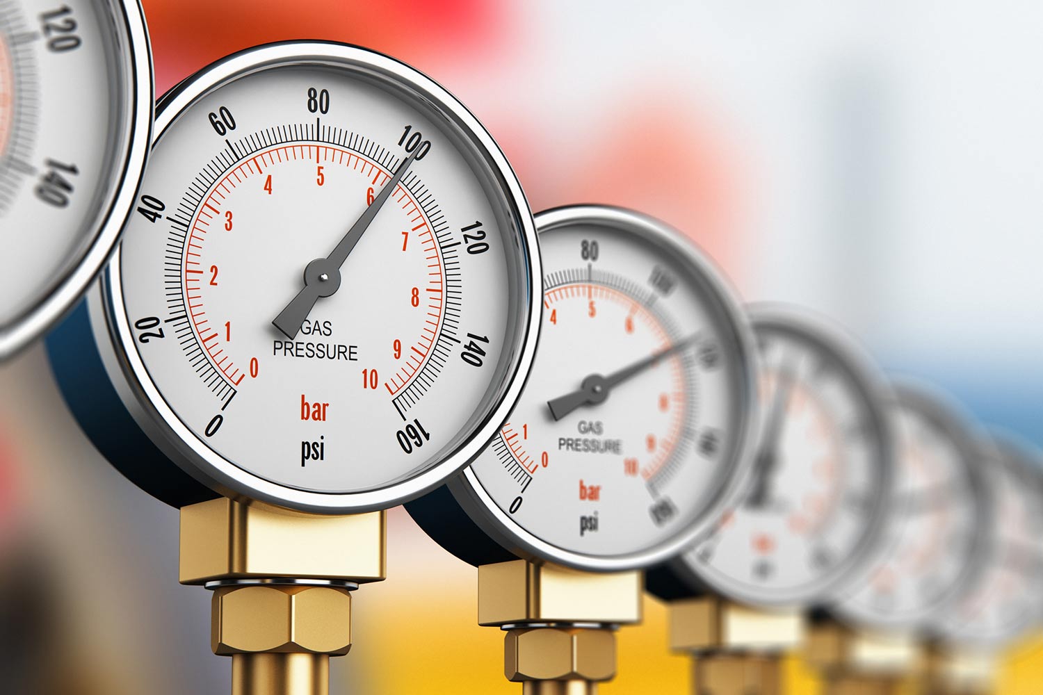
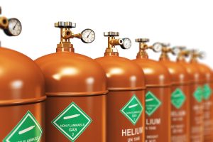
Pressurized gas represents one of the most challenging substances to contain in industrial applications. Unlike liquids, gases are compressible, can escape through the tiniest imperfections and their molecules—particularly in the case of helium, hydrogen and other light gases—can slip through microscopic spaces that would successfully contain liquids.
Industries that must contain gases rely on O-ring face seals to prevent product loss, improve safety, achieve environmental compliance, enhance system efficiency and in some cases, prevent catastrophic failures. O-ring face seal (ORFS) technology provides industrial gas handling with a sealing mechanism specifically designed to counter the natural tendency of gases to escape confinement.
ORFS fittings prove particularly effective by creating a dynamic seal that leverages the pressure of gases attempting to escape. As system pressure increases, the O-ring is forced more firmly against the sealing surfaces, improving the seal integrity. This “self-energizing” design has made ORFS fittings indispensable across numerous industries where gas containment is critical.
The Critical Role of ORFS Fittings in Industrial Gas Applications
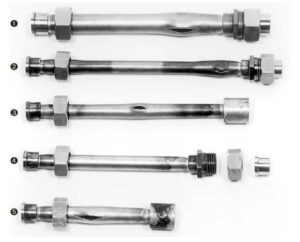
O-ring face seal fittings offer significant advantages over traditional compression or flare fittings, compressing an elastomeric O-ring between two flat metal surfaces, creating a seal. This design ensures that system pressure actually helps enhance the seal rather than compromise it – a phenomenon engineers refer to as “self-energizing.” As pressure increases within the system, the O-ring is pressed more firmly against the sealing surfaces.
CPV Manufacturing actually introduced new technology, its unique O-Ring Face Seal (ORFS) designs, to advance the effectiveness of o-rings. This innovation, featured in CPV’s O-SEAL® and Mark VIII® fitting lines, provides the appropriate sealing required for even the most challenging gases and fluids as well. This benefits multiple industrial applications where even minor leaks can result in lost revenue and pose severe safety implications.
These field proven case studies help illustrate the value of O-ring sealing solutions implemented across various gas-handling applications:
Industrial Gas: Containing Elusive Gases in Helium Compressor Systems
One of the most challenging applications for any gas sealing technology is the containment of helium, due to its small molecular size. At one gas filling plant in Boise, Idaho, the operator faced the challenge of efficiently filling helium cylinders for labs and welding operations.
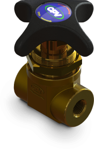
The helium from tube trailers is transferred and pressurized to 3,000 psi during off-hours and stored in exterior ground storage tanks, ready for the next day’s filling operations. The facility installed hundreds of CPV Manufacturing’s FloMaster® air-operated valves and O-Seal valves and fittings throughout their automated gas fill system to aid with secure gas transfer.
The results proved the value of this decision. The plant manager said, “FloMaster valves inside the plant, on the fill island, plus the FloMaster valves outside the plant on the ground storage tanks which are subjected to extreme Idaho winter weather conditions have all performed flawlessly since installation.” The superior sealing capabilities of the O-ring face seal design prevent the notoriously difficult helium from escaping, even under high pressure and variable environmental conditions.
The efficiency gained was measurable. The new valves enabled the operator to fill a 20-cylinder pallet of helium in 7 minutes compared to the 20-30 minutes of filling time using previous equipment.
Green Technology: High-Pressure CO₂ Refrigeration Systems
A US-based manufacturer has developed an innovative application that combines environmental sustainability with high-pressure gas handling, developing the first chiller system that utilizes CO₂ (R744) as a refrigerant. Part of this green technology’s viability relies on specialized fittings for high-pressure trans-critical CO₂ on the discharge side of the compressor.
The CO₂ refrigerant operates at significantly higher pressures than traditional refrigerants but offers a dramatically lower Global Warming Potential (GWP) of just 1, compared to common refrigerants like R404A with a GWP of 3,922. Mark VIII® fittings with stainless steel construction and Viton FKM® O-rings supplied by CPV helped this company to successfully meet the pressure and temperature requirements for this process.
This application demonstrates how O-ring face seal technology enables the development of more environmentally friendly industrial processes while maintaining the reliability needed for commercial success. The leak-free connections ensured by the ORFS fittings are particularly critical in refrigeration systems, where even small leaks can significantly impact system efficiency and environmental compliance.
Large-Scale Gas Filling Operations: Precision and Reliability in Mexico
In Santo Domingo, Mexico, one of North America’s largest fully automated, palletized specialty gas filling facilities depends on O-ring face seal technology for its operations. The facility fills more than 250 standard gas mixes for industrial, medical, welding, and other applications.
To meet international standards for mix accuracies established by NIST, EPA protocols, and USP grades, the facility implemented 180 CPV O-Seal valves throughout its operation. These air-actuated FloMaster O-Seal valves are used on all 18 automated heads on the platform to achieve instantaneous open/close operation on each filling location.
Gas mix accuracy depends on absolute precision in valve opening and closing, which is why the facility specified CPV O-Seal valves. The system is so reliable and user-friendly that the facility’s labor force, with minimal training, can operate it at 100% capacity. The sophisticated computer controls paired with leak-proof O-ring face seal technology allow the facility to complete 360 separate gas mix orders simultaneously, each with its unique formulation.
What Makes ORFS Fittings Essential for Gas Applications?
Several factors make O-ring face seal fittings the preferred choice for high-pressure gas applications:
- Vibration Resistance: Industrial gas systems often experience extreme torque and constant vibrations that can cause conventional fittings to shift and fail. ORFS fittings are designed to maintain their seal integrity even under these challenging conditions.
- Environmental Durability: Many gas systems must operate in harsh environments, including temperature extremes or corrosive conditions. The robust design of ORFS fittings with appropriate exterior plating ensures structural integrity in these settings.
- Ease of Installation and Maintenance: ORFS fittings allow for easy assembly and disassembly in the field, making replacement and repair simpler. This “slip-in slip-out” accessibility is particularly valuable in complex systems to help minimize downtime.
- Pressure Handling: ORFS fittings can reliably contain gases at pressures up to 7,500 psi, making them suitable for the most demanding high-pressure applications.
- Compatibility with Elusive Gases: The design is particularly effective with hard-to-contain gases like hydrogen and helium, which might escape through other sealing technologies.
The Engineering Considerations Behind ORFS Selection
When specifying ORFS fittings for gas applications, engineers must carefully consider:
- Material Selection: The O-ring material must be compatible with the gas being contained to avoid degradation and failure. Ask the experts at CPV to help match the appropriate O-ring material to the gas or liquid requiring containment.
- Temperature Range: Each O-ring material has specific temperature limitations that must align with the operational environment.
- Durometer (Hardness): This defines the compressibility of the O-ring material. The higher the number, the denser the material and the more difficult to compress.
- Gland Depth: Proper design ensures the O-ring doesn’t extrude into gaps between pressure points when subjected to high pressure.
Conclusion
These application examples help illustrate a few of the many ways that O-ring face seal fittings supply a small, yet indispensable piece of equipment utilized in industrial gas applications. From containing elusive helium to enabling green refrigeration technology and ensuring precise gas mixing, these sophisticated sealing solutions provide the reliability and performance required by modern industrial processes involving pressurized gas.
As industries continue to push the boundaries of pressure and temperature the role of O-ring face seal technology will continue to rise in importance. The ability to create and maintain leak-free connections under the most challenging conditions remains a critical factor for efficiency, safety and innovation across industrial gas applications. Questions about O-ring face seal technology? For more information about selecting the right ORFS fittings for your application, contact CPV Manufacturing’s technical support team at salesadm@cpvmfg.com.